Phase Linear 2000 Tone Control POP/THUMP

mslupczynski

New Around These Parts
Joined
Jun 4, 2023
Messages
10
#1
I'm rebuilding a PL2000 and during checkout it operates reasonably well in it's current state. Injecting a 1khz signal shows good signal flow etc., and overall I believe the unit is a good candidate for restoration and perhaps some opamp replacing from BrownDog to bring it up a level. As well as other mods I've seen out here that I'm continuing to research.

One thing I'm really wondering about - after a decent cleaning of the control pots and switches - there is still a very loud POP/THUMP when activating the tone control switch. I suspect more cleaning will not fix this and I'm wondering if it's maybe a cap issue. If so, perhaps this be alleviated when the responsible cap(s) in the tone control circuit are replaced?

If not, I'm pretty sure others have seen this issue and I'd love to know what might be causing it and if it has a known fix.

Thanks
 

George S.

Veteran and General Yakker
Joined
Feb 18, 2020
Messages
5,036
#2
I've three PL2000's, rebuilt stock or highly modified, all have a slightly momentary click of static when exercising the tone control switch. Very subdued and quiet.
Turn on thump is a different matter.
As a aside, not the resistor they used to jump across the power switch. The unit is always "on" in a reduced power status.
 

mslupczynski

New Around These Parts
Joined
Jun 4, 2023
Messages
10
#3
Thanks George... yeah, the THUMP is only on the tone control switch while the unit is powered on. I just figured this may be a common/know issue with the PL2000 preamp. The push-button switches themselves appear to be fairly generic and maybe tearing the TC switch apart might yield something?
 

laatsch55

Administrator,
Staff member
Joined
Jan 14, 2011
Messages
74,968
Location
Gillette, Wyo.
Tagline
Halfbiass...Electron Herder and Backass Woof
#4
Thanks George... yeah, the THUMP is only on the tone control switch while the unit is powered on. I just figured this may be a common/know issue with the PL2000 preamp. The push-button switches themselves appear to be fairly generic and maybe tearing the TC switch apart might yield something?
yep, lots of pieces...
 

mslupczynski

New Around These Parts
Joined
Jun 4, 2023
Messages
10
#5
LOL... ok, so are you saying it's a waste of time or be careful of "the pieces"... because that's never stopped me before when I was repairing watches. Perhaps I may have underestimated the complexity of these switches? :confused:
 

George S.

Veteran and General Yakker
Joined
Feb 18, 2020
Messages
5,036
#7
If it's a 2000 Series 2 with the Alps push button switches, they're easy to take apart and clean. The plunger and contacts pop out
I've a Series 1 with a different manufacturers switches, not Alps, distinctly different, not service friendly.
If Alps, I'd completely remove the switch board from the unit and take it apart inside a large plastic bag as there are springs.
That switch board wiring wasn't the best quality anyways. Probably starting to oxidize and corrode as were mine, new copper is needed.
Can't be more helpful, as I'm ass deep in home remodel project.
Getting plenty of listening time in though, mostly FM rock.
 

mslupczynski

New Around These Parts
Joined
Jun 4, 2023
Messages
10
#8
If it's a 2000 Series 2 with the Alps push button switches, they're easy to take apart and clean. The plunger and contacts pop out
I've a Series 1 with a different manufacturers switches, not Alps, distinctly different, not service friendly.
If Alps, I'd completely remove the switch board from the unit and take it apart inside a large plastic bag as there are springs.
That switch board wiring wasn't the best quality anyways. Probably starting to oxidize and corrode as were mine, new copper is needed.
Can't be more helpful, as I'm ass deep in home remodel project.
Getting plenty of listening time in though, mostly FM rock.
Perfect, thank you! That really helps me a bit more to understand what I'm facing. I love the plastic bag idea. I've lost plenty of springs and other parts by not somehow containing the disassembly. Cheers!
 

Gepetto

Administrator
Staff member
Joined
May 15, 2011
Messages
14,086
Location
Sterling, MA
Tagline
Old 'Arn Enthusiast
#9
It is likely caused not by the switch but instead by the offset of the 2 op amps feeding the final set of back to back output capacitors. If each has a different offset voltage, then the instantaneous voltage shift will be fed directly through those 2 output capacitors to the power amp. PL2000s that exhibit lower popping probably have op amps that are more closely matched to each other in offset voltage.

With no power amp connected to the preamp output and no signal into the preamp, measure the output voltage of Z3 pin 12 (tone out) and Z3 pin 10 (tone in) for the right channel and see how close they are.

Repeat the measurement for Z3 pin 3 (tone out) and Z3 pin 4 (tone in) for the left channel.

Using an op amp with lower offset voltages and lower input bias currents than the RC4136 may improve this situation

RC4136 - Vos = 0.5 to 6 mV, Ib = 140 to 500 nanoAmp all parameters at 25C

OPA2134 (on a brown dog adapter) - Vos = 1 to 3.5mV, Ib = 5 to 100 picoAmp (a huge difference, 28,000 times better)

Perhaps George can comment on this because I believe he changed out the 4136 for better op amps.

The situation may also be improved slightly by changing the 22K resistors in designators R57 and R65 to 82K instead.
 
Last edited:

wattsabundant

Chief Journeyman
Joined
Apr 26, 2011
Messages
941
Location
Central Ohio
#10
Sometimes you do things, not because you have to, but because you can. As I'm now retired I can take the time to mark up the schematic with Joe's comments. See attached.

I think I know opamp theory reasonably well, but the tone control schematic gives me a headache.

Joe, can you explain the logic behind the change of R57 and R65 to 82K?
 

Attachments

Gepetto

Administrator
Staff member
Joined
May 15, 2011
Messages
14,086
Location
Sterling, MA
Tagline
Old 'Arn Enthusiast
#11
Sometimes you do things, not because you have to, but because you can. As I'm now retired I can take the time to mark up the schematic with Joe's comments. See attached.

I think I know opamp theory reasonably well, but the tone control schematic gives me a headache.

Joe, can you explain the logic behind the change of R57 and R65 to 82K?
Because the bias current contributes to the offset of an op amp. If you have nominally the same bias currents for the inverting and non-inverting inputs to the op amp, you would like their bias current pathways to a low impedance source to be through resistors of nearly equal value, identical if possible. In the case of this circuit the path of R57 on the non-inverting input is obvious, 22K to ground. The pathway for the inverting input is from the output low impedance source, through R54 at 22K plus half of pot R53 for another 50K (half of the pot value), plus R51 at 10K. 22K + 50K + 10K = 82K. Matching R57 and that other chain that I just rattled off equal to each other will make the op amp output offset due to bias current effects lower.

It matters less when an op amp like the OPA2134 is used because the bias current is down in the low picoamp range. However when a high bias current op amp like the RC4136 is used, it matters much more.
 

mslupczynski

New Around These Parts
Joined
Jun 4, 2023
Messages
10
#12
I'm extremely thankful for the great insights and information posted here recently regarding this preamp restoration. Thank you for your time gentlemen. Yesterday I received most of the replacement capacitors but won't replace anything just yet. I also have some op amps on order from TI based on some research done here. As well as some DIP sockets.

I'm going to collect and document everything you've posted here - combined with my own notes - and write up a basic test plan. For anyone interested I'll post my plan and test results later. The great thing is the ability to easily get full access to the internals of the 2000 to test and dig deep.

Once I begin replacing components I'll bear in mind the soldering caveats mentioned in other posts. (i.e. too much heat loosening pads, traces, etc.)

More to come and thanks again!
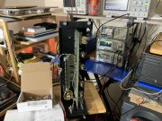
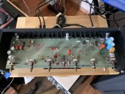
Phase Linear 2000 Preamp switch assy.jpeg Phase Linear 2000 Preamp main board.jpeg
 
Top