mslupczynski
New Around These Parts
- Joined
- Jun 4, 2023
- Messages
- 15
Happy New Year everyone!
Introduction and Question. (Hope I'm not breaking protocol by combining the two.)
I've been reading this forum for a couple years and until now was just gathering information and researching for my build pile. I've mainly been posting on AudioKarma for rebuild and trouble-shooting issues. I'm still learning how to write less and post more pictures and reference data to get better help. I have way too many unknown unknowns. Theoretically I have restored/rebuilt about 60 vintage units. Mostly Marantz, Pioneer, Sansui, McIntosh and Yamaha. (Honestly about a 80% success rate, some units still not fully figured out yet.) For instance, I just rebuilt a Yamaha CR2020 (power supply and regulator board and both output modules) and can't seem to figure out why one module still shorts the unit on DBT. With the module disconnected it's fine. Probably a short on the module but I can't seem to find it.) Anyway...
I've been sitting on two each Phase Linear 400's and 1 ea. 700B. It's time to get to work and already I'm finding that my 1st PL400 is a bit more challenging than anticipated. I started simple and already I'm puzzled. But I want to be cautious.
Scenario
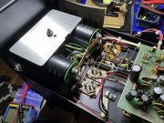
This 400 is super clean all original and in excellent condition with a beautiful wood case. Owner said it made a loud noise and he unplugged it and didn't use it again. First thing I did was test the original SANGAMD filter caps and one of them was completely shot. A detailed inspection of the driver board and internals shows no signs of burnt or discolored components. No arcing or loose wires. Very clean very original. Output transistor have not been checked yet.
So I got to work. Plan: Change caps and test.
1. Replaced both filter caps ( 2 ea. 100V 15,000 mf) and added the aluminum caps mounting plate
Since I'm already in here...
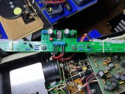
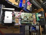
2. Installed a new light driver board from Watts (pic attached)
NOTE: When I attached the 5 wires to the light board (R, W, BL) and the 2 slightly bigger gauge Red wires (the instructions said the 2 Red wires were Gray, but mine are not.) So the only logical place for these Red wires was where the two Gray wires we slated to go. I could be wrong.
My plan was simply to replace caps, mod the lights and do a 1st power on test. Nothing else. Everything else in the unit is as the unit came, untouched.
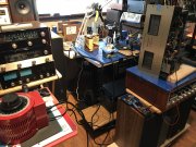
Test equipment: Variac, DBT, a couple of DMM's
Connected DBT to Variac, plugged PL400 into DBT, connected DMM on the filter caps to monitor voltage and slowly brought up power to slow charge caps and see if lights worked ok.
When I bring up power on the Variac the VU meters immediately come right up with the increases in power and I really only went to 50 volts or so on the variac before it was clear the VU meters would peg and that didn't seem right to me?
The 5 wires to the light/meter board IMO can only go on as I have them. I triple checked them and you can see from the pictures they are in per the board markings and the instructions. The caps are definitely taking a charge so I don't suspect anything there.
If anyone has seen this before with a new light/meter driver board on a PL400 I would really appreciate your insight. I hesitate to go any further until I'm confident I'm not over-driving the board somehow or perhaps there is something I'm over-looking.
Looking forward to a new year with new restoration adventures!
Thanks

