PL4000 rebuild

Overundr1

Journeyman
Joined
Sep 12, 2024
Messages
133
#1
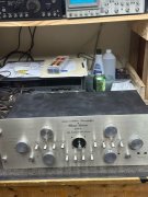
Finally starting in on the infamous pl-4000 pre amp.
The guilty suspect that was not happy with any board wriggling
1728232201426.jpeg

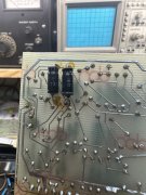
Main control board, complete reflow and test of every solder point and trace.

1728232242369.jpeg

Also verified every component on the front side and the usual electrolytic cap replacement.
1728232287877.jpeg

Front panel board, same as the control board, every solder point touched up and traces verified. Also just as I did on the control board clean and polish every pin as some did show minor oxidation. Also ran D5 through the rca jacks, thankfully none are damaged.


1728232416548.jpeg

And the front view, a couple of suspects replaced, complete DeOxit of switches and rotary potentiometers too.

1728232475859.jpeg

Now to move on to the rest of the boards.
 

Overundr1

Journeyman
Joined
Sep 12, 2024
Messages
133
#3
Appreciate the suggestions. Do you have a 'go to' for the pcb coating and as I am new to the Phase linear design, why the new rca jacks and is the set being offered by a seller on that auction site correct or is there a preferred replacement?. As a side note redoing all those connections was no-wheres near as tedious as re-pinning Sansui dolby boards, QRX boards or CA boards. Certainly would not attempt them without a digital iron and desolder station though.
 

marcok

Chief Journeyman
Joined
Jun 9, 2014
Messages
1,052
Location
Milan Italy
Tagline
I'm very curious about any tech item
#4
https://anasounds.com/produit/anasounds-sommercable-rca-female-connector-red/
Use this kind of connector and 2 short wires to connect it to the mother board .
Original connectors , after 50 years , have become fragile and when you insert a male connector ,
after 3 / 6 months they could break , causing bad contacts , low level distorsion .
Furthermore connectors are secured on the rear panel definitely much better than pcb .
For the paint something like this :
https://www.amazon.co.uk/s?k=clear+...ar+insulating+varnish+,aps,120&ref=nb_sb_noss
Paint only on the connectors . The contact between control board and mother board could be critical because
there are pc tracks inside the pins of the control board .
In PL , infact , in the third series they soldered together mother board and control board .
Anyway , years ago , I posted pics here in this forum .
Ciao
Marco
 

Overundr1

Journeyman
Joined
Sep 12, 2024
Messages
133
#7
That I do have. Now need to search out how those new connectors are set up.
Learned a long time ago doing it right means doing it once. This piece will be part of my extensive audio collection so no issues in getting everything correct.
 

George S.

Veteran and General Yakker
Joined
Feb 18, 2020
Messages
5,019
#11
On my modified Phase Linear 2000 Series 2 preamps, I remove the plastic jacks, crimp in eyelets to reinforce the traces.
Then install SwitchCraft jacks and insulators.
The original jacks are self shorting, so the ground wiring is different between the input and output jacks, using 20 AWG buss wire.
Shorting plugs go on any unused inputs.
I do like the plastic jacks for ease of disassembly, and they're OK with light weight thin interconnect cables.
But heavy cables wreck them and stress the board.
I did put NOS plastic jacks in the last preamp I rebuilt to original configuration, a 2000 Series 1.
 

Attachments

Last edited:

Overundr1

Journeyman
Joined
Sep 12, 2024
Messages
133
#14
Wondering why caps were arranged like this. Both +/- polarity in same direction same value both caps one on top one underneath to same solder points. In this case both are 1uf 35v why not use a single 2.2uf 50 on one side?
IMG_3477.jpeg IMG_3478.jpeg
 

Gepetto

Administrator
Staff member
Joined
May 15, 2011
Messages
13,927
Location
Sterling, MA
Tagline
Old 'Arn Enthusiast
#15
Wondering why caps were arranged like this. Both +/- polarity in same direction same value both caps one on top one underneath to same solder points. In this case both are 1uf 35v why not use a single 2.2uf 50 on one side?
View attachment 83603 View attachment 83604
They got a deal on 1uF caps :). What PL did often makes you scratch your head
 

Overundr1

Journeyman
Joined
Sep 12, 2024
Messages
133
#16
For extra bling used clear glossy gel nail polish oooh the shine :)
In other news did find several cold ring solder joints on the sub boards as I worked my way through them today.
Also had to touch up several traces that had cracks to ensure continuity.
Fun project.
 

marcok

Chief Journeyman
Joined
Jun 9, 2014
Messages
1,052
Location
Milan Italy
Tagline
I'm very curious about any tech item
#17
All caps must be minimum 50 V . PL introduced this mod after S/N 5000 .
Other suggestions :
Mother board and control board are " locked " with input selector and
volume pot , so it's necessary to assemble the faceplate to
have a steady mechanical config ( without bad conctacts )
Atfer insert tone board and logic board ( minimum config )
and check the normal functions .
Optional mod : I added two trims between main out aux out to have
fixed and variable outputs ( good for PL 400 )
The mod is very easy , since the outputs are connected with two wires .

Ciao
Marco
 

marcok

Chief Journeyman
Joined
Jun 9, 2014
Messages
1,052
Location
Milan Italy
Tagline
I'm very curious about any tech item
#18
Replace the relay for switched outlets with a 24V 16A type with a 470 Ohm 1W in series
with the coil . It's undersized ( another time bomb ) See PL 4000 service manual rev. 6 81.
That's all folks ! ( if my memory served me )
Ciao
Marco
 

marcok

Chief Journeyman
Joined
Jun 9, 2014
Messages
1,052
Location
Milan Italy
Tagline
I'm very curious about any tech item
#19
Better to assemble the bottom cover to lock everything .
This is my story of my PL 4000s ( 2 units ) and one PL 1000 .
Anyway everything is written between the lines of service manuals .
( I believe there are 3 versions and the most complete edition is the rev .6 81 .
Ciao
Marco
 

Overundr1

Journeyman
Joined
Sep 12, 2024
Messages
133
#20
Have a good paper copy of the service manual that came with the pre amp. Quite a treat to read one written with English as the writers native language. Somewhat surprised there is no parts list. Is there an accepted relay that fits without having to dead bug the leads and any other known troublemakers I should be glaring at as I complete my Mouser order today? Also hoping that my shop quickly returns to the not a hair salon manly solder fumes odor after the generous application of nail polish yesterday :)
As a side note I have all the caps on hand (low esr/MUSE/WIMA film etc etc) but of course they are all radial and not too happy with the idea of having them all with long leads on the circuit boards. The 50v reminder was appreciated although uprating caps has become standard rework practice these days.
And what are those control knobs made of, they are in dire need of polishing so any tips would be appreciated.
-Lee
 
Top