New PL400 Full WOPL Build

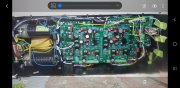
This is what I observed in original setup, the tape did not securely hold the caps in-place and they shifted over time:

IMG_5196-X2.jpg


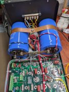
You can also slot the holes in the buss bar and roll the caps so the buss bar comes down...
 
Question regarding DCP board wire connection for Ground.

What is the recommended connection point for J3-2 Ground when using Joe's backplane boards, GND_OUT1?

As well as Fused_B+_Out for J3-1, DC Input?

DCP%20Wire%20Connections-S.jpg

IMG_5522-X2.jpg
 
Last edited:
Question regarding DCP board wire connection for Ground.

What is the recommended connection point for J3-2 Ground when using Joe's backplane boards, GND_OUT1?

As well as Fused_B+_Out for J3-1, DC Input?

DCP%20Wire%20Connections-S.jpg

IMG_5522-X2.jpg
The "Star" point - the copper (or aluminum) bus bar between the PS capacitors.
Fused B+ pad in the top right corner of that board in your picture - mean to put that in my initial reply.
 
Thanks for the input and clarifications.

After rereading several documents and staring at the rats nest of wiring, I made small progress today.

IMG_5544-X2.jpg

IMG_5538-X2.jpg

IMG_5541-X2.jpg

IMG_5542-X2.jpg
 
And as Gene stated today in another thread, you'll need a B+ wire to the DCP. Best place to attach it is the top right corner of the right back plane. May as well solder it in now before proceeding.
 
Here's a old photo, the green wire to the DCP.
 

Attachments

  • PXL_20220606_210027666.jpg
    PXL_20220606_210027666.jpg
    1.9 MB · Views: 45
And as Gene stated today in another thread, you'll need a B+ wire to the DCP. Best place to attach it is the top right corner of the right back plane. May as well solder it in now before proceeding.
Thanks, that will be the next thing I’ll complete.
 
Here's a old photo, the green wire to the DCP.
Is there a reason you did not run the AC and Ground return together?

I realize DC and Grounds typically run down the bottom of the chassis, but aren’t you creating a rather large loop by running the AC feed on top and Ground return on bottom?

I guess my question should be, is J3-2 an AC Ground return, DC Ground return, or both. As well as, is the current small enough not to worry about how it’s placed in this application.
 
Last edited:
That's a old 400 WOPL build, from before Joe put together his multimedia 400 build montage.
We builders used to run the AC line legs across the top of the left back plane, then down to the thermobreaker.
So, AC was run across the top, DC across the bottom.
And I always felt, the DCP grounds should be in the lower DC bundle, as they all attach to the copper buss bar, aka star ground. This was discussed before at some point, I forget where.
 
Thank you for the continued feedback. Given this is my first build, sometimes it's helpful to talk through pros/cons of different methods to help prevent Marvin from completing his mission.

Pictures help tremendously.

I plan to run the DCP AC feed down the center (bundled with Thermal Switch wiring) and Ground along the bottom.
And your AC feed to the DCP should come from the provision made for this on the snubber board.
 
And your AC feed to the DCP should come from the provision made for this on the snubber board.
Complete - Purple wire.

Every time I look at that old double sided tape, I think I should have removed when I had the cradle off the transformer.

IMG_5549-X2.jpg
 
Only advantage I know of is needed clearance between the meter stud and copper buss bar. You can lower the buss bar by moving the caps further apart using the original holes on the original buss bar, or craft a new bus bar with the holes closer together.
Easiest and cheapest to just get the old tape off the cradle, and watch clearance during assembly. The 400 and 700 Series 2 have no tape, they used a clamp attached to the rectifier stud.
Wish I had a photo of a original 400 S2, but here's a photo of the copper strap/clamp I made for my 700 Pro build. Those caps are right against the aluminum cradle, no padding.
 

Attachments

  • PXL_20211226_203205440.jpg
    PXL_20211226_203205440.jpg
    2.9 MB · Views: 21
Back
Top