phase linear 400

gene french

Veteran and General Yakker
Joined
Mar 6, 2022
Messages
5,578
Location
guayabo de bagaces, guanacaste, costa rica....
Tagline
music...the healer of souls...
Care and attention to details = great final result and a totally boring bring up (a good thing).

You have a couple of mysteries in life going on there Gene but I will get over those.
life has a way of messing with our minds sometimes....
i am so consumed with this and other things in my life....it is so difficult to sleep....
but, i would not have it any other way....
and feel bad for those with nothing to think about...
lololol
 

gene french

Veteran and General Yakker
Joined
Mar 6, 2022
Messages
5,578
Location
guayabo de bagaces, guanacaste, costa rica....
Tagline
music...the healer of souls...
It's looking better. 4 things.
1. The flying yellow output wires need to be above all other wiring.
2. The LED board wiring needs to run over the top of the amp. You'll put a soft cloth on the heatsinks, set the faceplate on the cloth upside down and vertical with something like a can of beverage or whatever behind it to hold it up right. Then complete the faceplate wiring(when your ready). Then lift the faceplate up and simply rotate the top(which is the actual bottom) towards you as you sit it down in place to the chassis. Get and keep that wiring over the top for now.
3. The wiring along left side of the right backplane needs massaged into position better. Keep it more in that gap between the board edge and thermo breaker.
4. Your DCP grounds that run across the bottom look too long, but probably aren't if you position them more under the DCP, then up to the DCP. Work on getting those also looking good. Joe said he used small wood dowels to bend radiuses on wire. I do the same but use a plastic coated handle on wire cutters or needle nose or round shank of a long Phillips bit screwdriver.
I see no wiring errors, but I'm on a phone.
At this point, or when you run out of things to do, check your power supply for +-80 VDC. BUT FIRST, disconnect from the caps and that AC connection on the DCP. Be carefull, don't burn up your hard work. Earlier you said you were only getting +-60 VDC. Go back and find that post and my photo if your not totally sure how to.
explain number 2....
i did not want to run the meter outputs down with the same wire as the ac to the led board....so they are free until they meet at the bar??
is that not satisfactory??
thanks
 

gene french

Veteran and General Yakker
Joined
Mar 6, 2022
Messages
5,578
Location
guayabo de bagaces, guanacaste, costa rica....
Tagline
music...the healer of souls...
explain number 2....
i did not want to run the meter outputs down with the same wire as the ac to the led board....so they are free until they meet at the bar??
is that not satisfactory??
thanks
just trying to keep ac/dc seperated....i guess that is dc being measured at the meters???
as i was told to do....i am a good boy....lol
 

gene french

Veteran and General Yakker
Joined
Mar 6, 2022
Messages
5,578
Location
guayabo de bagaces, guanacaste, costa rica....
Tagline
music...the healer of souls...
Some procedures (like applying power early on) need to be hidden as some guys are not that far advanced. I've had one or 2 bad power ups in 7 years and it was my fault not procedure/parts failure. I don't even bring up one row at a time anymore, I populate outputs (all of them) and bring it up once but not all of the guys CAN. I never bring up just the back plane, and never just the control board. If it aint ready for the whole thing to power up, IT AINT READY!!! :)
i got a lot more checking and stuff i want to do before i light her up....i dont want to blow this one up...lol
i have time....plenty of time.....i want it to be the best it can be....
thanks for your comments...
 

gene french

Veteran and General Yakker
Joined
Mar 6, 2022
Messages
5,578
Location
guayabo de bagaces, guanacaste, costa rica....
Tagline
music...the healer of souls...
It's looking better. 4 things.
1. The flying yellow output wires need to be above all other wiring.
2. The LED board wiring needs to run over the top of the amp. You'll put a soft cloth on the heatsinks, set the faceplate on the cloth upside down and vertical with something like a can of beverage or whatever behind it to hold it up right. Then complete the faceplate wiring(when your ready). Then lift the faceplate up and simply rotate the top(which is the actual bottom) towards you as you sit it down in place to the chassis. Get and keep that wiring over the top for now.
3. The wiring along left side of the right backplane needs massaged into position better. Keep it more in that gap between the board edge and thermo breaker.
4. Your DCP grounds that run across the bottom look too long, but probably aren't if you position them more under the DCP, then up to the DCP. Work on getting those also looking good. Joe said he used small wood dowels to bend radiuses on wire. I do the same but use a plastic coated handle on wire cutters or needle nose or round shank of a long Phillips bit screwdriver.
I see no wiring errors, but I'm on a phone.
At this point, or when you run out of things to do, check your power supply for +-80 VDC. BUT FIRST, disconnect from the caps and that AC connection on the DCP. Be carefull, don't burn up your hard work. Earlier you said you were only getting +-60 VDC. Go back and find that post and my photo if your not totally sure how to.
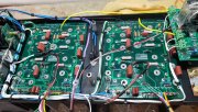
thanks mr. george for hanging in there with me...
i appreciate your help and confidence in me...
 

gene french

Veteran and General Yakker
Joined
Mar 6, 2022
Messages
5,578
Location
guayabo de bagaces, guanacaste, costa rica....
Tagline
music...the healer of souls...
It's looking better. 4 things.
1. The flying yellow output wires need to be above all other wiring.
2. The LED board wiring needs to run over the top of the amp. You'll put a soft cloth on the heatsinks, set the faceplate on the cloth upside down and vertical with something like a can of beverage or whatever behind it to hold it up right. Then complete the faceplate wiring(when your ready). Then lift the faceplate up and simply rotate the top(which is the actual bottom) towards you as you sit it down in place to the chassis. Get and keep that wiring over the top for now.
3. The wiring along left side of the right backplane needs massaged into position better. Keep it more in that gap between the board edge and thermo breaker.
4. Your DCP grounds that run across the bottom look too long, but probably aren't if you position them more under the DCP, then up to the DCP. Work on getting those also looking good. Joe said he used small wood dowels to bend radiuses on wire. I do the same but use a plastic coated handle on wire cutters or needle nose or round shank of a long Phillips bit screwdriver.
I see no wiring errors, but I'm on a phone.
At this point, or when you run out of things to do, check your power supply for +-80 VDC. BUT FIRST, disconnect from the caps and that AC connection on the DCP. Be carefull, don't burn up your hard work. Earlier you said you were only getting +-60 VDC. Go back and find that post and my photo if your not totally sure how to.
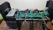
with control board just sitting there for you to see how i wired led board
 

Attachments

George S.

Veteran and General Yakker
Joined
Feb 18, 2020
Messages
5,036
Gene, it's looking better, but you now have that black AC wire to the DCP running very close to your speaker jacks. Better to pull it out from under the DCP and run it parallel with the DCP board edge, with a small gap. Maybe run it a little below that edge to keep it away from the other wiring.
On the meter wiring. Easiest way I've found is sit the amp on the bench normal, on its feet. Put a soft cloth on top of the heat sinks. Now place the faceplate on the soft cloth, with the inside of the faceplate facing up or facing at you with a support. Then wire it with correct length of wire.
This ensures wire lengths are long enough for easy servicing.
To put a built amp into the service position.
1. Remove the top chassis cover.
2. Place a soft cloth on the heatsinks.
3. Remove the faceplate bolts and flip the faceplate up and over onto the soft cloth.
4. Amp is now in service position with no stress on the wiring or scratching the faceplate.
I don't see a 22 AWG ground wire for the meters. That's a small solder hole on the LED board.
 
Joined
Mar 6, 2022
Messages
359
Location
Minnesota
Tagline
Always Thinking Outside The Box.
i think its right music man....
but, i will give it all a good going over before i put on the control board...
tip is unfused...
shell is fused...
etched into my memory...
Gene
Not talking about the Fuses, I think you wired to the output and should be wired to the Input.
 

Attachments

gene french

Veteran and General Yakker
Joined
Mar 6, 2022
Messages
5,578
Location
guayabo de bagaces, guanacaste, costa rica....
Tagline
music...the healer of souls...
Gene, it's looking better, but you now have that black AC wire to the DCP running very close to your speaker jacks. Better to pull it out from under the DCP and run it parallel with the DCP board edge, with a small gap. Maybe run it a little below that edge to keep it away from the other wiring.
On the meter wiring. Easiest way I've found is sit the amp on the bench normal, on its feet. Put a soft cloth on top of the heat sinks. Now place the faceplate on the soft cloth, with the inside of the faceplate facing up or facing at you with a support. Then wire it with correct length of wire.
This ensures wire lengths are long enough for easy servicing.
To put a built amp into the service position.
1. Remove the top chassis cover.
2. Place a soft cloth on the heatsinks.
3. Remove the faceplate bolts and flip the faceplate up and over onto the soft cloth.
4. Amp is now in service position with no stress on the wiring or scratching the faceplate.
I don't see a 22 AWG ground wire for the meters. That's a small solder hole on the LED board.
its there..in the bottom bundle with dcp grounds...connect to led harness an end...but its there...i tucked the ground wires under dcp...will reposition black ac wire as you suggest
 

gene french

Veteran and General Yakker
Joined
Mar 6, 2022
Messages
5,578
Location
guayabo de bagaces, guanacaste, costa rica....
Tagline
music...the healer of souls...
Gene
Not talking about the Fuses, I think you wired to the output and should be wired to the Input.
ok...i will pull docs tomorrow..i want to recheck the wiring before moving to control board!!!
you dont know how much i appreciate all of these eyeballs!!!!
 

George S.

Veteran and General Yakker
Joined
Feb 18, 2020
Messages
5,036
Gene, I believe Steve has found a wiring error and did a great job identifying it. I think there's two ways to wire these backplanes. Run long wires from the right backplane, or "daisy chain" the right backplane to the left with short pieces of wire.
Thought about asking Joe about this several times, but never got around to it.
 
Top