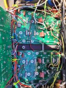
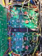
I took on this project. Where to start? Need to know the status of the driver board. Howe to test it? I've been wanting to build a test set for a long time. This is the right excuse.
Started hunting around the shop. Figured I'd mkae a single channel amp with one NPN and one PNP output. I have a box of complimentary outputs, 2N5631 (NPN) and 2N6031 (PNP) from the days of testing Dynaco 400 driver boards. Checked them on a curve tracer and they looked to be OK. Found a heatsink for 4 x TO3's. Not very big which is good as it won't run long enough to heat up. Found a 70VCT transformer. A couple snap in caps and Joe's adaptor board. Used a 10amp bridge rectifier. A piece of 3/4" plywood that didn't need to be cut down.
View attachment 65225
View attachment 65226
Built the power supply first and got +/- 50 VDC at 120 VAC input. Mounted the board and made up the connections from the outputs and drivers to the to the right channel of the board. Used the same wiring color convention for the board as the back planes. Since it follows the resistor color code it doesn't require any thought once the brown wire is landed.
Issues found:
First off the Phoenix connectors for the bias transistor was mounted on the front of the board. They are supposed to be on the back. In this case it made it easy to temporarily connect a bias transistor that had been pulled from a working amp. The leads on the bias transistor were intact. Eventually the Phoenix bias transistor connectors will get moved to the back of the board.
Not to begin testing. Brought up the power supply through a 100W bulb. No +15V power supply. Found D83 installed backwards. Now +15V supply Ok but no -15VDc on pin 4 of the opamp. Found R40 missing. Installed resistor and got output but positive cycle truncated. Found R35 on both channels missing. This supplies + VDC to the collector of the positive predriver (Q6).
The channel then worked at no load but went into current limit and was unstable with load. For some reason I had picked the value for the output emitter resistor as 1.2 ohms. Changed them to 0.22 ohms. Negative half cycle was ok but positive unstable with high frequency oscillations. It was 3:00 AM at that point. Called it a night. On the way to bed realized I hadn't put in a zobel.
today I repurposed a zobel that had been removed removed during a relay board install.. That tamed the oscillations.
Moved all of the driver board wiring from the right channel to the left channel. Didn't have any +/- 15 VDC. Realized I had to jumper +/- 75VDC from left channel to the right channel to get +/-15 vdc. Left channel worked ok.
So now that I know the driver board works I can redo the back plane.
Throughout all of this, the amp has been on the back edge of the bench while I worked on the test set. A like minded friend looked at the chassis and noticed one of the fuse holder didn't look right. We assumed someone put in a 1.25" AGC fuse rather than the 1" AGX fuse that belongs there. Pulled it out and found a piece of sheet copper that had been fashioned as a fuse. I've seen foil wrapped around a fuse. Never a piece of copper. A new standard has been set.
Now to remove and reinstall the back plane mess.
View attachment 65228View attachment 65225View attachment 65226View attachment 65228


![IMG_4061[1].JPG IMG_4061[1].JPG](https://forums.phxaudiotape.com/data/attachments/61/61973-cdd4c26e74b8402ff2a5c57741ef33db.jpg?hash=zdTCbnS4QC)
![IMG_4063[1].JPG IMG_4063[1].JPG](https://forums.phxaudiotape.com/data/attachments/61/61974-3b379989b95f77723e933126f648baaf.jpg?hash=OzeZiblfd3)
![IMG_4057[1].JPG IMG_4057[1].JPG](https://forums.phxaudiotape.com/data/attachments/61/61976-4bd8b2af303ad18b510dace21e864179.jpg?hash=S9iyrzA60Y)
