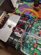
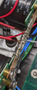
I may need some assistance. My 4-Fin White Oak 400 has been working great for over a year until earlier this week. This unit has the Rev E Control Board, Rev C Backplanes, Cap Upgrade, LED Light Board, and DCP board. When I turned it on everything appeared normal, but the protection relay would not enable. I checked the rail fuses and both were good. This is a later 4-Fin where the capacitors and bridge rectifier mount to the transformer.
I opened it up for a quick inspection and found the -15V was missing at the test point on the Control Board. The minus side pico fuse was open on the right channel backplane. I pulled the Control Board out for inspection. I performed a quick DMM diode test on the -15 power supply semiconductors and all passed and were the same as the +15 side. I performed a quick resistance check of the resistors and no problems were identified. I also looked for questionable joints and connections and none were found. Next I went back to the BOM to ensure the resistors were indeed correct in the voltage regulator section and the entire board. Everything looked good.
I bridged the blown -15V pico fuse with a 0.5A AGC fast blow fuse in series with a Fluke 89 meter reading milliamps. I slowly brought the unit up with a variac and dim bulb monitoring current through the fuse. I also monitored the +15V and -15V test points. The unit came up perfectly the the protection relay enabled as it should. Readings were:
+15V: 15.10V
-15V: -15.13V
Fuse Current: 18.51mA
Next I set the Fluke meter to record the maximum transient current during power on. When switched on the transient current through the -15V fuse recorded 370mA.
I powered everything down. Removed the fuse and measured resistance from the control board terminal 11R to ground. Next I manipulated the backplane boards and the control board to see if something was shorting from movement. The resistance did not change so I don't feel something is shorting to ground.
My question to the experts is: What would you advise next? I suspect the in-rush current is fatiguing the pico fuse over time.