The DCP ground is paired with DC, NOT ACAt the time that I was running the ground wire I was thinking it paired with the DC. Then the next step had me running the AC wire and I didn't think much of it. I just mounted the DCP board and terminated the connections for the first time last night and got a better feel for how it works.

You are using an out of date browser. It may not display this or other websites correctly.
You should upgrade or use an alternative browser.
You should upgrade or use an alternative browser.
phase linear 400
- Thread starter gene french
- Start date
gene french
Veteran and General Yakker
- Joined
- Mar 6, 2022
- Messages
- 5,884
- Tagline
- music...the healer of souls...
yes, i knew that joe was gepetto....i understand he is the whiz kid of the phase linear legendary accomplishments....i sincerely appreciate all of his wisdom he has generously shared with me....and i knew also he was mr. oak, white oak that is....Gene, Joe is Gepetto here on the site and he's the reason most of us are here on this site keeping the Phase Linears alive and he supplies us with all the upgrade parts (He's White Oak Audio). Get out the credit card and finish buying the upgrade parts so that 40 year old amp quits fuckin with your brain (It will blow again, it's just a matter of weeks).
CHER????
HUH?
")
for now, i dont think i want to upgrade this 400....i think i want to keep this one stock ... i did get joes light BOARD kit, and the power supply upgrade capacitor kit...and the dc protect board...so i dont burn down the barn, so to speak...i want this as a token of the sound i fell in love with in the early to mid 70s.. with safety compensated for with the upgrades....
i think i want to upgrade a 700b or possibly another 400 ....i asked the group about a cheap one i found...but, was advised to not get a 4 fin...i will pick up the search when i finish with this one...or find a deal i cant pass up.....i have a few spare parts i have accumulated...but, i was told there are great similarities in the two lines of phase linear...
CHER...joe is a first name and no last name....as cher has one first name and no last name...that was an attempt at ironical satire...i must have failed...lol
i do appreciate your help and advice!!!
thanks to all
ABebar
Journeyman
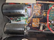
Lol, I now see on post #221, 228/229 he caught this error and reran (facepalm). That was 8 minutes and four zip ties that I'll never get back.The DCP ground is paired with DC, NOT AC
https://forums.phxaudiotape.com/threads/pl-700-pro-build.9965/page-12
ABebar
Journeyman
There is one more thing I was curious about... I thought I was being smart but now I'm thinking that I might be making more trouble for myself in the very near future.
I am currently leaving out the middle heat sinks so that I have better access to the transistor mounting holes. It's really easy when you have clear access. My plan was to continue to bring up the amp back plane one row at a time until they were all in, then temporarily remove those four screws threaded into the standoffs and mount the heat sinks back in. I thought I was being smart and dealing with the four standoffs would be easier than fishing 16 transistors into a narrow space one at a time. Now I'm thinking that lack of access to the standoffs behind the backplane board might make it impossible to lock these screws back in without direct access. Perhaps I could thread a screw in from the top while I back the screw out the bottom to hold it in place, then do the reverse after the heat sink is installed? Has anyone tried this before? I would hate to get all four rows in and then realize that I need to pull them back out to install the two little heat sinks, but I'm starting to think that's exactly what is going to happen.
Any thoughts?
- Joined
- Jan 14, 2011
- Messages
- 75,834
- Location
- Gillette, Wyo.
- Tagline
- Halfbiass...Electron Herder and Backass Woof
Fight the good fight and dont mess with the heatsinks..
- Joined
- Jan 14, 2011
- Messages
- 75,834
- Location
- Gillette, Wyo.
- Tagline
- Halfbiass...Electron Herder and Backass Woof
Those heatsinks are either bonded or glued somehow. Every set I've taken off are really stuck and you may compromise heat transfer more than it is already..
WOPL Sniffer
Veteran and General Yakker
There is one more thing I was curious about... I thought I was being smart but now I'm thinking that I might be making more trouble for myself in the very near future.
I am currently leaving out the middle heat sinks so that I have better access to the transistor mounting holes. It's really easy when you have clear access. My plan was to continue to bring up the amp back plane one row at a time until they were all in, then temporarily remove those four screws threaded into the standoffs and mount the heat sinks back in. I thought I was being smart and dealing with the four standoffs would be easier than fishing 16 transistors into a narrow space one at a time. Now I'm thinking that lack of access to the standoffs behind the backplane board might make it impossible to lock these screws back in without direct access. Perhaps I could thread a screw in from the top while I back the screw out the bottom to hold it in place, then do the reverse after the heat sink is installed? Has anyone tried this before? I would hate to get all four rows in and then realize that I need to pull them back out to install the two little heat sinks, but I'm starting to think that's exactly what is going to happen.
Any thoughts?
or, use the telescoping magnet output installer and be done with it
ABebar
Journeyman
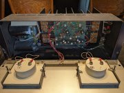
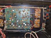
Hmmm... These came off really easily. They weren't bonded together at all except for some old heat sink compound. The heat sinks are basically four separate pieces of rolled steel formed into two different pairs of "U" shapes. When I pulled the old transistors out the heat sinks came apart from the chassis. I was able to wash and dry them separately and then reinstall the two larger outside ones, but I left the two smaller ones (between columns 1/2 and 3/4) removed.Those heatsinks are either bonded or glued somehow. Every set I've taken off are really stuck and you may compromise heat transfer more than it is already..
Attached is a pic from when I first fitted in the back plane boards with the two larger heat sinks installed. The two smaller ones are somewhat visible in the lower left-hand corner next to the faceplate.
Attachments
ABebar
Journeyman
I thought I found a shortcut. I should have known it was too good to be true. I have heard fishing these in is a bit of a headache and I thought I discovered a workaround. I'll revert back to the traditional way. Thanks for the feedback.or, use the telescoping magnet output installer and be done with it
Correct Lee, they are glued together with thermal glue...Adam I have no idea what you have there...other than to use Perry's term. Huh??Those heatsinks are either bonded or glued somehow. Every set I've taken off are really stuck and you may compromise heat transfer more than it is already..
ABebar
Journeyman
:-/
I suppose my question has changed then... When I put these back together, should I do anything to increase the thermal transfer? I suppose I'll reapply some heat sink compound, but it really is just those two screws holding the small U heat sinks in place.
I suppose my question has changed then... When I put these back together, should I do anything to increase the thermal transfer? I suppose I'll reapply some heat sink compound, but it really is just those two screws holding the small U heat sinks in place.
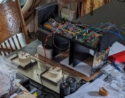
2" diameter bulk caps???Hmmm... These came off really easily. They weren't bonded together at all except for some old heat sink compound. The heat sinks are basically four separate pieces of rolled steel formed into two different pairs of "U" shapes. When I pulled the old transistors out the heat sinks came apart from the chassis. I was able to wash and dry them separately and then reinstall the two larger outside ones, but I left the two smaller ones (between columns 1/2 and 3/4) removed.
Attached is a pic from when I first fitted in the back plane boards with the two larger heat sinks installed. The two smaller ones are somewhat visible in the lower left-hand corner next to the faceplate.
- Joined
- Jan 14, 2011
- Messages
- 75,834
- Location
- Gillette, Wyo.
- Tagline
- Halfbiass...Electron Herder and Backass Woof
Yes and yes..
- Joined
- Jan 14, 2011
- Messages
- 75,834
- Location
- Gillette, Wyo.
- Tagline
- Halfbiass...Electron Herder and Backass Woof
:-/
I suppose my question has changed then... When I put these back together, should I do anything to increase the thermal transfer? I suppose I'll reapply some heat sink compound, but it really is just those two screws holding the small U heat sinks in place.
Yes and yes...
WOPL Sniffer
Veteran and General Yakker
I thought I found a shortcut. I should have known it was too good to be true. I have heard fishing these in is a bit of a headache and I thought I discovered a workaround. I'll revert back to the traditional way. Thanks for the feedback.
After years of the guys on these pages coming up with procedures for upgrading or just repairing these amps, all of these "Shortcuts" "New Ideas" have all been explored with varying degrees of success. Use the traditional (Normally used) methods and go for it. Just a tip, tie up all those wires or you'll be chasing broken solder joints by the bushel. There is safety in numbers and I always tie my wires to prevent damage. Building these amps may look easy but it aint and when you are finished, the bad practices stand out like a broken pecker. Clean clean clean, tie tie tie etc.....
WOPL Sniffer
Veteran and General Yakker
WOPL Sniffer
Veteran and General Yakker
I'm anal.... I go through hundreds of zip ties and I may put 10 ties on, reroute one wire, and cut the ties all off, and then tie them up again (MANY TIMES). Nothing worse than a wad of wires you can't look at and trace if needed and puts the pro touch to it.
gene french
Veteran and General Yakker
- Joined
- Mar 6, 2022
- Messages
- 5,884
- Tagline
- music...the healer of souls...
it does look nice...I'm anal.... I go through hundreds of zip ties and I may put 10 ties on, reroute one wire, and cut the ties all off, and then tie them up again (MANY TIMES). Nothing worse than a wad of wires you can't look at and trace if needed and puts the pro touch to it.
ABebar
Journeyman
These pictures are from when I first received the amp and cracked her open:2" diameter bulk caps???
Attachments
ABebar
Journeyman
I have the serial number written down as 7A11091
Whoops, wrong one, that was from a 700s2. The 400 serial number is 17056.
Whoops, wrong one, that was from a 700s2. The 400 serial number is 17056.
Last edited: