Nice 400-ll to rebuild

grapplesaw

Veteran and General Yakker
Joined
Aug 13, 2014
Messages
2,786
Location
Vancouver
Tagline
---
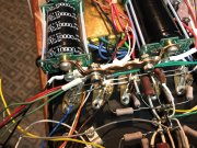
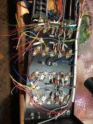
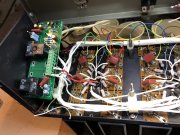
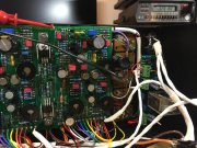
My next amp is going to be a 400-ll. It is in good condition and has somewhat rare long fin in full extrusion format heat sinks. The person ( only initials -BR- on tag) who built it took quite a lot of pride on the original build as you can see by the tidy wiring of which I have already started to mess up. Not may hours on this puppy as you can see the lack of any heat discoloration of the control board.

this will be my tweeter amp for the corner horns in a tri amp setup

I may use a D board or a G board. I like the sound of the D and love the channel seperate on of the G. Decision yet to be made

I will add a few tricks so follow along
61291C81-325E-4B97-AD98-6E343C6AAF2C.jpeg86672616-799A-45FF-A3A9-AD1DC41C76F7.jpegF90D0AC0-42FA-4F27-918D-BDCCF646CEA3.jpegFAE347FE-7706-42F7-B5CC-61593E135A10.jpeg
 
So first mod is to add a fifth output to the row. We saw this done before on a custom build by ? Forgot his name.

I did up a pair of carver c-500’s. It has 5 outputs per channel so wanted to try one. Using the approach from above design (see photo) i am adding a pair of mjl21195/96 to each channel. Just sorting best location now. EE010408-8BE3-41BF-ABD7-4BA09D69F854.jpeg39FC9019-7E15-4DC4-984C-DFE537CBBE0B.jpeg1E7DD325-3331-4AF1-9CAE-BDD0767C440B.jpeg
 
Holy mad scientist Batman, that is some cool shizzle right there.
Glen, can you explain what your going after with your mods please?
I am just being curious and amazed.
 
Holy mad scientist Batman, that is some cool shizzle right there.
Glen, can you explain what your going after with your mods please?
I am just being curious and amazed.
first the photo of the control board is from this thread

https://forums.phxaudiotape.com/thr...wer-amplifier-–-refurbished-on-ebay-now.8765/

Steve Mantz did it. read the thread and ignor the negative stuff. There is some good stuff there’s.

now what I am up to is to do what I did to the C-500’s

here are some photos
 

Attachments

  • A4C7B79B-4C21-44AC-963F-C7A34DD628F7.jpeg
    A4C7B79B-4C21-44AC-963F-C7A34DD628F7.jpeg
    1.1 MB · Views: 50
  • 83F565DD-53FF-4118-BC34-0D49390D68B0.jpeg
    83F565DD-53FF-4118-BC34-0D49390D68B0.jpeg
    1.2 MB · Views: 55
  • DC7F8D3A-24C9-45E3-B5E1-7DD4A98B28B8.jpeg
    DC7F8D3A-24C9-45E3-B5E1-7DD4A98B28B8.jpeg
    922.3 KB · Views: 56
  • 21200E2E-0A0B-4393-B401-8EC6D1AA5447.jpeg
    21200E2E-0A0B-4393-B401-8EC6D1AA5447.jpeg
    843.9 KB · Views: 52
Very cool Glen, I like this mad scientist stuff. Your really pushing the modification boundaries. Keep the info coming.
 
George I also change almost all the fuse holders now to AGC You cannot put a AGC fuse in a AGX holder and I would advise against putting a AGX in. AGC holder.

this amp is so unused I will reuse the old ones with main power AGC and rails AGX78D22F68-E4C0-449D-8763-FAA57274E55F.jpeg
 
In the thread someone said “So he added 4 additional output transistors (2 per channel) to a 400 series one, what will this achieve?”

well my reasoning is why not - the more outputs the lower distortion. It’s not about more power

also may be a better load share in 4 ohm setting
 
Last edited:
Back
Top