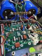
New 700b WOPL build... blowing fuse 2 on left backplane

dtafil

Journeyman
Joined
Jan 23, 2020
Messages
101
#1
Hey guys - Been a while. Still enjoying the heck out of my WOPL'ed 700b... so much so that I wanted 2, lol.

In any event, following the bring up routine for my new, full WOPL build, as follows:

1. Populated bottom row of transistors, floated star ground, bringup slowly on Variac w/ dim bulb. Passed, DC protection relays click. No blown fuses.
(Discharged bulk caps)

2. Same as #1, but connect single star ground. Bringup slowly on Variac w/ dim bulb. Passed, DC protection relays click. No blown fuses.
(Discharged bulk caps)

3. Added driver board, all connections. 500 mA fuse (F2) on Left backplane blows.

I did replace the fuse, hung a multimeter across F2, slowly bring up system w/ Variac & dim bulb. DC mV climbing across F2. Powered down before fuse popped. I did check all other voltages across other fuses, they remain at ~0.1 mV DC throughout.

Any suggestions on where to begin debug? No destroyed silpads this time ;-)

Will add some pics if there's an area of interest.

Thanks guys!
 
Last edited:

George S.

Veteran and General Yakker
Joined
Feb 18, 2020
Messages
5,036
#3
Your positive a bias transistor isn't shorting on a P strap, and you've looked the board over under magnification for solder whiskers, splatter and correct components in proper location and orientation?
 
Last edited:

Gepetto

Administrator
Staff member
Joined
May 15, 2011
Messages
14,065
Location
Sterling, MA
Tagline
Old 'Arn Enthusiast
#4
Hey guys - Been a while. Still enjoying the heck out of my WOPL'ed 700b... so much so that I wanted 2, lol.

In any event, following the bring up routine for my new, full WOPL build, as follows:

1. Populated bottom row of transistors, floated star ground, bringup slowly on Variac w/ dim bulb. Passed, DC protection relays click. No blown fuses.
(Discharged bulk caps)

2. Same as #1, but connect single star ground. Bringup slowly on Variac w/ dim bulb. Passed, DC protection relays click. No blown fuses.
(Discharged bulk caps)

3. Added driver board, all connections. 500 mA fuse (F2) on Left backplane blows.

I did replace the fuse, hung a multimeter across F2, slowly bring up system w/ Variac & dim bulb. DC mV climbing across F2. Powered down before fuse popped. I did check all other voltages across other fuses, they remain at ~0.1 mV DC throughout.

Any suggestions on where to begin debug? No destroyed silpads this time ;-)

Will add some pics if there's an area of interest.

Thanks guys!
RevG1 control board Dave? Or E6? It matters to help your debug.
 

dtafil

Journeyman
Joined
Jan 23, 2020
Messages
101
#5
May as well start with good high res photos of all areas of the control board. Both sides.
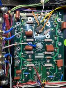
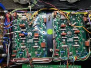
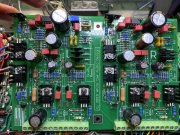
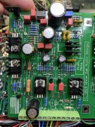
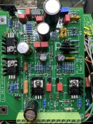
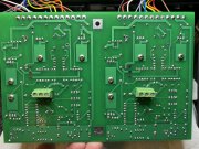
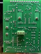
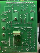
Hi @George S. - Thanks for the suggestions. Bias transistors are clear of the P-straps, nothing touching there. Boards were cleaned, leads on the back planes trimmed nice and close to ensure no shorts. Top side high-res pics attached of those to start:
 

Attachments

Last edited:

George S.

Veteran and General Yakker
Joined
Feb 18, 2020
Messages
5,036
#9
Been working all day and only have a smartphone.
Only thing that stands out to me is where the red bias wire is soldered on the left backplane. Did this wire break off during assembly and a new connection was soldered with the back plane in place. If so, perhaps the broken wire end and or solder is grounding out against the chassis.
Also, I assume you are using the assembly aid bolts to hold the back plane in place. You do have the nylon insulating washers installed.
Lastly, I would remove the output transistors and see if the fuse still blows. If it still blows, there are voltage test points you can compare between each channel to narrow the issue.
 

dtafil

Journeyman
Joined
Jan 23, 2020
Messages
101
#10
No worries at all. The extra solder on the red wire was simply a bit more than I would have liked when soldering in from the rear of the backplane, but looks better to the eye than that picture. And yes, the backplanes are held down from the aluminum standoff and screw (from beneath) with a nylon washer, fender washer, star ground and nut on the top side. I'll pull the backplanes tomorrow. I've also got some spare bias transistors, so I can pull and test those 2 if needed.
 

laatsch55

Administrator,
Staff member
Joined
Jan 14, 2011
Messages
74,939
Location
Gillette, Wyo.
Tagline
Halfbiass...Electron Herder and Backass Woof
#11
I would isolate the backplanes as in the bringup test to see if the problem is with the backplanes before I pulled em.,../
 

Gepetto

Administrator
Staff member
Joined
May 15, 2011
Messages
14,065
Location
Sterling, MA
Tagline
Old 'Arn Enthusiast
#12
Hi Dave
Couple of questions and suggestions to help debug.

The bias transistor is connected to the 3 pin Phoenix connector when you are doing this bring up correct?

With the bias transistor connected and powered off, ensure by ohming out that the wire connection from the backplane to the control board is good for each of the 3 wires.

If all good with that, I would recommend simplifying the problem by isolating things. First suggestion is to temporarily lift one end of R8L and note if the problem persists or not. This temporary action will isolate if you have a short somewhere on the board on the output of the -15V regulator.

If no change results, then you know that the problem is either within the -15V regulator circuit or in the B- feed to Q3-5
 

dtafil

Journeyman
Joined
Jan 23, 2020
Messages
101
#13
Hi Dave
Couple of questions and suggestions to help debug.

The bias transistor is connected to the 3 pin Phoenix connector when you are doing this bring up correct?

With the bias transistor connected and powered off, ensure by ohming out that the wire connection from the backplane to the control board is good for each of the 3 wires.
Morning Joe -

Yes, bias transistor connected to rear Phoenix connectors.

Ohm'ed out the connection of each bias transistor leg to it's corresponding Phoenix connector. Got the following readings:

Left:
C: 441K ohms
B: 0.2 ohms
E: 379K ohms

Right:
C: 441K ohms
B: 0.2 ohms
E: 382K ohms

If that looks good, I'll move on to R8L...
 

Gepetto

Administrator
Staff member
Joined
May 15, 2011
Messages
14,065
Location
Sterling, MA
Tagline
Old 'Arn Enthusiast
#14
Morning Joe -

Yes, bias transistor connected to rear Phoenix connectors.

Ohm'ed out the connection of each bias transistor leg to it's corresponding Phoenix connector. Got the following readings:

Left:
C: 441K ohms
B: 0.2 ohms
E: 379K ohms

Right:
C: 441K ohms
B: 0.2 ohms
E: 382K ohms

If that looks good, I'll move on to R8L...
Hi Dave
Perhaps you misunderstood what was being asked. It should be near zero in each measurement.

Emitter on bias transistor to Emitter at Phoenix connector
Base on bias transistor to Base at Phoenix connector
Collector on bias transistor to Collector at Phoenix connector
 

dtafil

Journeyman
Joined
Jan 23, 2020
Messages
101
#15
Hi Dave
Perhaps you misunderstood what was being asked. It should be near zero in each measurement.

Emitter on bias transistor to Emitter at Phoenix connector
Base on bias transistor to Base at Phoenix connector
Collector on bias transistor to Collector at Phoenix connector
Hi Joe -

I think I did just that (?)

For example, bias transistor on left backplane measurement: Multimeter set to ohms. Attached one probe lead (mini-pincher from the multimeter) to the emitter leg of the bias transistor; used the other probe lead (from multimeter) to measure ohms at the corresponding (Phonenix) connector on the control board for that emitter connection.

Does that sound right?
 

Gepetto

Administrator
Staff member
Joined
May 15, 2011
Messages
14,065
Location
Sterling, MA
Tagline
Old 'Arn Enthusiast
#16
Hi Joe -

I think I did just that (?)

For example, bias transistor on left backplane measurement: Multimeter set to ohms. Attached one probe lead (mini-pincher from the multimeter) to the emitter leg of the bias transistor; used the other probe lead (from multimeter) to measure ohms at the corresponding (Phonenix) connector on the control board for that emitter connection.

Does that sound right?
Yes, it sounds right Dave. You are measuring a wire connection in this case. A wire should measure near zero on each of those readings.
 

dtafil

Journeyman
Joined
Jan 23, 2020
Messages
101
#17
I did pull one of the legs for R8L... same behavior. Bulb glowing on bring up with the control board attached, mV growing across F2. I assume I should reconnect that resistor at this point (?) - or, I can go back and simply measure the wire-to-wire connection points only if that's helpful?
 
Last edited:

Gepetto

Administrator
Staff member
Joined
May 15, 2011
Messages
14,065
Location
Sterling, MA
Tagline
Old 'Arn Enthusiast
#18
I did pull one of the legs for R8L... same behavior. Bulb glowing on bring up with the control board attached, mV growing across F2. I assume I should reconnect that resistor at this point (?) - or, I can go back and simply measure the wire-to-wire connection points only if that's helpful?
Your connection readings to the bias transistor are definitely a big concern Dave. Do you have a diode scale on your meter that beeps for continuity? You should get a beep on each one of those bias transistor wire connections.
 

dtafil

Journeyman
Joined
Jan 23, 2020
Messages
101
#19
Your connection readings to the bias transistor are definitely a big concern Dave. Do you have a diode scale on your meter that beeps for continuity? You should get a beep on each one of those bias transistor wire connections.
I do indeed. Will check those out over lunch. Appreciate your time as always.
 

WOPL Sniffer

Veteran and General Yakker
Joined
Aug 10, 2015
Messages
11,522
Location
Minnie-Soda
Tagline
Screw it
#20
The wires going to the Bias EBC on each back plane , the insulation should not be touching the pads on the component or solder side of the board.
 
Top