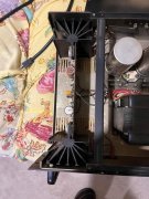
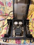
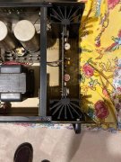
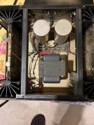
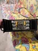
Leach amplifier?

jhsellers

New Around These Parts
Joined
Jul 29, 2020
Messages
10
Location
North Georgia
#1
Hello, all.

Wondered if anybody here has experienced the Leach amp?
http://leachlegacy.ece.gatech.edu/lowtim/

The late Marshall Leach was my advisor when I was in school. He was considered an eminent authority on audio technology in his time, but I've no idea how that equates to recent advances in equipment. I built his pre-amplifier design as my senior project, but never got around to building the amp. Several of my colleagues built the amp; output power was only limited by the size of transformer you wanted to splurge for (rail voltage, and TX capacity). (as well as the number of final stage transistors, of course )

I have a couple of boards for the amp driver circuit; I'd be glad to let them go for shipping cost if anyone's interested. It might take me a bit to locate - I'm in the process of moving everything; relocation due to recent retirement - so I'm not sure how quickly I can find them. ( and please realize that they're 40 years old too.....)

Leach also had speaker designs that he made public. There is no telling how many of these speakers are still around - I recall almost everyone saying they had built a pair of his speakers. I also fondly remember his lab at Georgia Tech - it was a showcase for state-of-the-art audio during the last quarter of the 20th century.

Reminiscing a bit.....
John
 

mlucitt

Veteran and General Yakker
Joined
Jun 24, 2011
Messages
3,469
Location
Jacksonville, FL
#4
Hello, all.

Wondered if anybody here has experienced the Leach amp?
http://leachlegacy.ece.gatech.edu/lowtim/

The late Marshall Leach was my advisor when I was in school. He was considered an eminent authority on audio technology in his time, but I've no idea how that equates to recent advances in equipment. I built his pre-amplifier design as my senior project, but never got around to building the amp. Several of my colleagues built the amp; output power was only limited by the size of transformer you wanted to splurge for (rail voltage, and TX capacity). (as well as the number of final stage transistors, of course )

I have a couple of boards for the amp driver circuit; I'd be glad to let them go for shipping cost if anyone's interested. It might take me a bit to locate - I'm in the process of moving everything; relocation due to recent retirement - so I'm not sure how quickly I can find them. ( and please realize that they're 40 years old too.....)

Leach also had speaker designs that he made public. There is no telling how many of these speakers are still around - I recall almost everyone saying they had built a pair of his speakers. I also fondly remember his lab at Georgia Tech - it was a showcase for state-of-the-art audio during the last quarter of the 20th century.

Reminiscing a bit.....
John
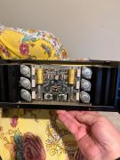
I could not find a value for R51, the ground compensating resistor on the amp boards, in the parts list. Perhaps you have more detail than the web page shows?

This is the reference:
"The circuit board has two ground leads, both of which connect to the central power supply ground. One lead grounds the signal reference points for the diff amp input stage. The other grounds the power supply decoupling capacitors and provides a ground reference for the protection circuit. R51 connects the two ground leads together on the circuit board. This resistor is small enough to look like a signal short circuit between the two grounds but large enough to force the currents in the two grounds to flow to central ground through the separate wires. This helps to prevent hum induced by power supply ripple currents in the ground system."

I have used these ground compensating resistors in my rebuilds, but the consensus on this forum is that they are not needed. I prefer to agree with Professor Leach, that using these resistors 'might' prevent hum induced by the power supply. They can't hurt, in my opinion.

Thanks,
Mark
The Mad Grounder
 

jhsellers

New Around These Parts
Joined
Jul 29, 2020
Messages
10
Location
North Georgia
#6
I could not find a value for R51, the ground compensating resistor on the amp boards, in the parts list. Perhaps you have more detail than the web page shows?

This is the reference:
"The circuit board has two ground leads, both of which connect to the central power supply ground. One lead grounds the signal reference points for the diff amp input stage. The other grounds the power supply decoupling capacitors and provides a ground reference for the protection circuit. R51 connects the two ground leads together on the circuit board. This resistor is small enough to look like a signal short circuit between the two grounds but large enough to force the currents in the two grounds to flow to central ground through the separate wires. This helps to prevent hum induced by power supply ripple currents in the ground system."

I have used these ground compensating resistors in my rebuilds, but the consensus on this forum is that they are not needed. I prefer to agree with Professor Leach, that using these resistors 'might' prevent hum induced by the power supply. They can't hurt, in my opinion.

Thanks,
Mark
The Mad Grounder
Mark,

Sorry, but I have no more information readily available - save what you've already studied on the GT.edu site. I only have the circuit boards from my own ambitions to someday build one of Leach's amplifier designs. Never made judicious downloads of the build notes, although I probably should have. Seems there are quite a few hyperlinks on the archived website that don't work any more. I'm not sure what protection is built into his design, although I should have remembered that there are a couple of distinct units he worked with. One is the Low-TIM distortion design, that's referenced on the main page you've seen. There is another amplifier that followed this Low-TIM amp - that one is more comparable to Phase Linear units - the Leach Superamp.

I made a rough search after reading your post, and didn't even find the reference for R51 that you quoted. I even tried to read the color bands on the photo shot of the assembled board (you can find R51, but resolution doesn't make the bands decipherable). However, from your quoted text, I'll hazard a guess - using my experience as a power system engineer, and protection for ground faults.

Trying to guesstimate current needed to "invoke/trip" a fault protection circuit, I would say that R51 should be somewhere in the neighborhood of 20-30 ohms (assuming DC rail voltages of +/- 60-65 V). This should look like just a shunt to ground for noisy ground loop current - mA range, drain the hum away? And yet it should limit any larger fault current to no more than a few amps, which "SHOULD" trip a protection feature. (Probably shouldn't hazard that guess if I can't inspect the protection circuit myself, but I'm not an analog transistor guru..... I'm not sure where to even look for this type of feature..... )

That's not going to give you any more than what you could surmise yourself. But, if you were to put such a resistor in the design, that's what I'd recommend. (feel free to embarrass me if I'm way off here - maybe R51 should be a small fraction of what I'm guessing?)

Hope this helps, (and nice to know I hooked you into such a detailed look-see....) :)
John
 

mlucitt

Veteran and General Yakker
Joined
Jun 24, 2011
Messages
3,469
Location
Jacksonville, FL
#8

jhsellers

New Around These Parts
Joined
Jul 29, 2020
Messages
10
Location
North Georgia
#9
John, I just found these on a deep dive:
The schematic on this page (left side) shows R51 as 82R, (8.2 Ohms).
http://www.pavouk.org/hw/leachamp/en_index.html

The 700W version schematic shows R51 as 10R (1 Ohm)
http://electronics-diy.com/electronic_schematic.php?id=988

I have used 4.7 Ohm resistors in the 400W amp, so I guess I'm in the ballpark. I am assuming the value is not critical unless there is a ground fault, in which case the 1/4 Watt resistor will probably lose it's life.

Mark
Nice digging, Mark. Yep, those resistors are used as fuses. Is that the protection, or is there another part of the design that acts from a fault?

Thanks, I learned something from discussion with you.

Best,
John
 

mlucitt

Veteran and General Yakker
Joined
Jun 24, 2011
Messages
3,469
Location
Jacksonville, FL
#11
I believe Leach used a protection circuit similar to the Phase Linear amps. A pair of complementary transistors (one for each polarity) that are operated by limiting current coming from the output transistors to turn off the pre-driver transistors until the current on the outputs is reduced.

Mark
 

nakdoc

Chief Journeyman
Joined
May 11, 2011
Messages
633
Location
Nashville, TN Music City
Tagline
highly biased
#12
I built the little Leach preamp with good results. my friend Bob Hoover made a 6 watt true class A power amp using the same topology, and it was state of the art (back in 1978)
 

83teq

New Around These Parts
Joined
Oct 12, 2020
Messages
1
#13
I owned the Leach LSR&D stereo amp back in the 80's and they sucked. Dry, cold sound! Leach does not believe in matching transistors.
 

wattsabundant

Chief Journeyman
Joined
Apr 26, 2011
Messages
932
Location
Central Ohio
#15
I seem recall the Leach amp in Audio magazine. I may still have the edition it was introduced and will search for it. As for matching transistors, I don't believe it's necessary in a proper design. A proper design takes into account that there are differences in production runs of components and the design should remain stable if the components are within a reasonable tolerance.
 
Top