First Time Building PL400 BP Rev B

Phantom Lamb

New Around These Parts
Joined
Mar 22, 2020
Messages
6
#1
All,

New to the forums and wanted to reach out. Have recently acquired the BP to help my dad finish this project that both of us have been working on for a while. I have been provided with the attached along with the board, components, soldering iron, and multimeter.

My biggest concern is soldering the solder cups before putting on the components. Any tips/help would be much appreciated as I don't want to trash this board!

Thanks,
 

Attachments

MarkWComer

Veteran and General Yakker
Joined
Nov 1, 2014
Messages
3,251
Location
Gaston, SC
Tagline
Victim of the record bug since age five
#2
I used an old washcloth under the board to keep them pushed up from behind to solder them in.
Solder from the edge so you don’t fill the holes, you usually get one extra in the package in case you accidentally ruin one in the process.

It’s the PEM nuts that I hate. LOTS of HEAT on those, and keep them flush with the board so your collector screws won’t go in crooked.
 

Gepetto

Administrator
Staff member
Joined
May 15, 2011
Messages
13,553
Location
Sterling, MA
Tagline
Old 'Arn Enthusiast
#3
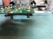
A trick for the PEM nut soldering, hang the screws in the kit below the board while soldering. Keeps tension on them and keeps them straight while soldering.
IMG_1970.JPG IMG_1975.JPG
 

MarkWComer

Veteran and General Yakker
Joined
Nov 1, 2014
Messages
3,251
Location
Gaston, SC
Tagline
Victim of the record bug since age five
#4
WHOA! STOP!
Forget what I said about the washcloth- that’s what I did for the components.

I used a wood block and a record clamp:


Gepetto

Administrator
Staff member
Joined
May 15, 2011
Messages
13,553
Location
Sterling, MA
Tagline
Old 'Arn Enthusiast
#5
Glad you clarified that Mark.

The masking tape shown in the instructions provided works best for the socket cups. It prevents any possibility of getting solder into the entry end of the socket cups. The exit end of the socket cups are plugged by organic plug material. DO NOT REMOVE those plugs during any board assembly steps. They will be removed automatically when you install the transistors.
 

Phantom Lamb

New Around These Parts
Joined
Mar 22, 2020
Messages
6
#6
Thanks guys, this has been a huge help so far.

I am currently on the PEM soldering and these things are a bear. I soldered some crap joints last night just to adhere them to the board and will be doing clean up today or tomorrow.

I was thinking of just screwing in the screws completely to the PEM nuts to put tension on them. Aside from these screws getting really hot, is there any reason this shouldn't work?

Thanks,
 

laatsch55

Administrator,
Staff member
Joined
Jan 14, 2011
Messages
74,254
Location
Gillette, Wyo.
Tagline
Halfbiass...Electron Herder and Backass Woof
#7
Nope..
Nav-Linear came up with some clamps I use and they were plastic, using plastic screws. They're good for 10 solderings.
Just remember to make sure the solder gets to the other side...
 

Mohawk

Chief Journeyman
Joined
Oct 29, 2019
Messages
603
Location
Ontario Canada
#8
The only issue I see with using the hex screws to hold in the PEN nuts is the screws will "wick up " some of the heat needed for a solid bonded connection !
If you have a lower wattage iron this approach might not work out .....

M
 

Gepetto

Administrator
Staff member
Joined
May 15, 2011
Messages
13,553
Location
Sterling, MA
Tagline
Old 'Arn Enthusiast
#9
Doing so means you will be removing the Kapton tape on the top of each risking:

  1. Solder buildup on the end face of each which is bad
  2. Solder in the threads which is bad
  3. Screw soldered to nut which is the combination of 1 and 2 above, also bad.
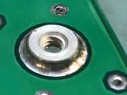
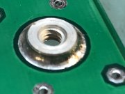
Solder joints must be nice or you will have issues. Solder joints should look like the attached when you are complete all 32 or 48 solder joints.
IMG_1974.JPG
 

Phantom Lamb

New Around These Parts
Joined
Mar 22, 2020
Messages
6
#10
So moving along in the build I made a pretty dumb mistake and accidentally added R6 to one of the boards and am now short a resistor R5 on the other board.

Thinking I should just snip it and try to solder in the best as possible or order more resistors?

Thoughts? You guys have been a huge help so far, thanks for everything.
 

WOPL Sniffer

Veteran and General Yakker
Joined
Aug 10, 2015
Messages
11,231
Location
Minnie-Soda
Tagline
Screw it
#11
Glad you clarified that Mark.

The masking tape shown in the instructions provided works best for the socket cups. It prevents any possibility of getting solder into the entry end of the socket cups. The exit end of the socket cups are plugged by organic plug material. DO NOT REMOVE those plugs during any board assembly steps. They will be removed automatically when you install the transistors.

Joe, are those solder cups really gold? After a Shit-Load of wopls, I got a baggie with a bunch in there........ Maybe I'll make me a nose ring?????
 

WOPL Sniffer

Veteran and General Yakker
Joined
Aug 10, 2015
Messages
11,231
Location
Minnie-Soda
Tagline
Screw it
#12
So moving along in the build I made a pretty dumb mistake and accidentally added R6 to one of the boards and am now short a resistor R5 on the other board.

Thinking I should just snip it and try to solder in the best as possible or order more resistors?

Thoughts? You guys have been a huge help so far, thanks for everything.

Unsolder it. This is where 2 irons work the best.
 

MarkWComer

Veteran and General Yakker
Joined
Nov 1, 2014
Messages
3,251
Location
Gaston, SC
Tagline
Victim of the record bug since age five
#15
Look for a vacuum desoldering tool, looks like a syringe.
It gets most of the solder, usually enough to make the job easier.
Your BOM has all the part numbers listed, it helps to order replacements for some things like the pico fuses. Sometimes Mouser may be out of stock, but the part numbers also work at Digi-Key.
 

laatsch55

Administrator,
Staff member
Joined
Jan 14, 2011
Messages
74,254
Location
Gillette, Wyo.
Tagline
Halfbiass...Electron Herder and Backass Woof
#16
Understood. I'm having trouble unsoldering it as the lead hole in the board is ridiculously small.
Warm up one lead and pull it. Warm up the other lead and pull it. Then desolder the remaining solder. Desoldering and pulling a resistor should not be that difficult..
 

Wheel-right

Chief Journeyman
Joined
Jun 24, 2019
Messages
781
Location
SoCal
Tagline
Man, Ya shoulda been here yesterday
#17
Nope..
Nav-Linear came up with some clamps I use and they were plastic, using plastic screws. They're good for 10 solderings.
Just remember to make sure the solder gets to the other side...
Would you happen to have a pic of those clamps? Might try making something up. Thanks
 

J!m

Veteran and General Yakker
Joined
Dec 24, 2019
Messages
9,426
Location
Connecticut
Tagline
BOT
#20
I have had good luck desoldering by getting it molten and blowing it out with an air gun. I don’t think “canned air” (or Perriair from Spaceballs) would work.

Sometimes takes a couple tries but it works. Feels nice when it splashes on you too.
 
Top