- Joined
- Jan 14, 2011
- Messages
- 75,833
- Location
- Gillette, Wyo.
- Tagline
- Halfbiass...Electron Herder and Backass Woof
Sil-pads are the way to go now. Berquist..

I still have a bunch of new MJ21196 that were never used, I would only need the`95s.
The 2n6254s that were in there were mounted with a mica and some type of silicone pad with no thermal paste, should the new transistors be mounted the same way or with the more traditional mica/paste combination?
OkThanks for that grapplesaw. I have been unable to find any documentation pertaining to the comp version. Would you have a scan of those? I cant quite expand the image enough.
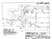
Here are the schematics. Try downloading them to get clearer imageThanks for that grapplesaw. I have been unable to find any documentation pertaining to the comp version. Would you have a scan of those? I cant quite expand the image enough.
Most of us here use silpads alone, no grease, no mica.The 2n6254s that were in there were mounted with a mica and some type of silicone pad with no thermal paste, should the new transistors be mounted the same way or with the more traditional mica/paste combination?
Yup!She's a beauty.
Thanks for thatHere are the schematics. Try downloading them to get clearer image
") .
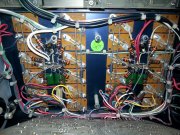
.Yes those are delegated by factory. These are the fly back diodes. Much debate as to there requirement in full complimentary setup but Joe said they will not hurt so I add them. I don’t think Ed likes them put in. Your choiceThanks for that
A quick look and I see a few discrepancies, the schematic shows D107,D108. Those seem to be MIA but there are two 10R resistors instead. The IC in the control board is different from that in the diagram too.
The ic should be lf351 and resistor r1 and r2 should be 7.5k 3 watt ( I use 5 watt or greater) with that opamp.Thanks for that
A quick look and I see a few discrepancies, the schematic shows D107,D108. Those seem to be MIA but there are two 10R resistors instead. The IC in the control board is different from that in the diagram too.
Yes, that checks out.The ic should be lf351 and resistor r1 and r2 should be 7.5k 3 watt ( I use 5 watt or greater) with that opamp.
You got a hell of a good amp there. If you can do the rest of the WhiteOak upgrade you will have an amp to last for the next 50 plus years.Yes, that checks out.