WOPL update for PL400

BlueCrab

Journeyman
Joined
Nov 10, 2019
Messages
229
#1
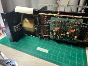
I'm beginning a WOPL update for this old PL400 (and before I get it in the ear from WOPL Sniffer about why I didn't do it for a PL700, it's because I choose to ;-) ). This one is just starting to suffer from corrosion on all the hardware and the transformer, so first step is to tear it apart and treat that and replace the hardware. Looks like this PL400 was treated about 20 years ago - some of the electrolytic caps on the PL14 card have date codes from the mid 90's.

One of the questions I have is, has anyone tried installing panel mount circuit breakers instead of the fuse holders? I plan to replace the AGX fuse holders anyhow, but it would be nice to use CBs instead, particularly for the AC power where it could operate as a poor man's on/off switch.
 

Attachments

oldphaser

Chief Journeyman
Joined
Sep 8, 2012
Messages
845
#3
I can't quite make out the brand of electrolytic capacitors you have in the power supply in your amp. My best guess at the moment is STM. Is this correct? If so, you might consider replacing them.

Although some on this forum might like to replace the AGX fuse-holders because they think the fuses are hard to find..... you can find them in Bussman MKG-7 "motorcycle kit" which includes (1) AGX5 and (2) AGX8 fuses at some local auto stores. Dean Nissen (the last Phase Linear factory service manager at the Lynnwood, Washington plant) and I use MCM 5A 250V (part # 28-0420) and MCM 8A 250V (part number 28-0435) as replacements for the AGX5's and AGX8's.

The fuse-holders originally used by Phase Linear were HJM (for AGX) and HKP's (for AGC).


Ed
 

Gepetto

Administrator
Staff member
Joined
May 15, 2011
Messages
13,566
Location
Sterling, MA
Tagline
Old 'Arn Enthusiast
#4
AGX fuses are available in abundance on Mouser, 5A and 8A ratings in large quantities.
 

BlueCrab

Journeyman
Joined
Nov 10, 2019
Messages
229
#5
Yes, the caps are STM and they will be replaced. I've ordered replacements from White Oak.

With regard to the fuse holders, I am considering replacing them with circuit breakers such as these from Mouser - W28-XQ1B-8 (or 5 amp versions for the B+ and B- legs). The issue is they take a larger hole - 0.625" vs 0.5" for the original fuse holders. Just wondering if anyone else has gone down this path. The circuit breakers cost all of $3 to $4 bucks, would eliminate the need to stock fuses, give an immediate indication that it has popped, and for the AC, provides a poor man on-off switch.
 

Gepetto

Administrator
Staff member
Joined
May 15, 2011
Messages
13,566
Location
Sterling, MA
Tagline
Old 'Arn Enthusiast
#6
Circuit breakers usually have a long trip curve (on purpose) on them when compared with cartridge fuses. The original 5A AGX are very fast blow instrumentation type fuses. You may find that the circuit breakers in place of the rail fuses don't protect much if something bad occurs. The TE datasheet comes right out and says that they replace SLO-BLOW cartridge fuses giving you an idea of the trip curve.

You may also experience arc flash problems when the contacts open since these are placed on DC rails. That does not happen with glass cartridge fuses since they are one time.

It is your amp so you can clearly do what you desire, I wouldn't recommend it for the above reasons

On the AC main, you will likely be OK.
 

BlueCrab

Journeyman
Joined
Nov 10, 2019
Messages
229
#7
Appreciate the input and this is what I'm looking for - pros and cons. Given that they replace slo-blow puts the nail in the coffin for the DC. But for the AC main, I may do it for the reasons I stated above.

Interesting what you state concerning arc flash problems, since all the aircraft systems on which I worked most of which are 28vdc and many handle far greater current than this amp, I've never come across this. Pilots and mechanics routinely use these circuit breakers as switches, so those CBs get cycled thousands of times. Not to say they don't go bad - they do - but I haven't heard of this. Learn something new everyday.
 

BlueCrab

Journeyman
Joined
Nov 10, 2019
Messages
229
#9
Same info for the AGX fast acting fuses. Shows that a 5 amp fuse will blow in 1 second with an 8 amp load. For the CB to act in 1 second the load would have to be between 300% (15 amps) to 500% (25 amps) for a 5 amp rated CB.
1576804177231.png
 

Gepetto

Administrator
Staff member
Joined
May 15, 2011
Messages
13,566
Location
Sterling, MA
Tagline
Old 'Arn Enthusiast
#10
Same info for the AGX fast acting fuses. Shows that a 5 amp fuse will blow in 1 second with an 8 amp load. For the CB to act in 1 second the load would have to be between 300% (15 amps) to 500% (25 amps) for a 5 amp rated CB.
View attachment 38317
That 25A cited interrupts in 25 milliseconds for the AGX fuse, 40 times faster than the CB. A lot of semiconductor damage can happen in even 25 milliseconds.

Your arc flash is against a nominal 80-100VDC across the contacts when they are forced to open due to an overcurrent situation. That voltage is small compared to the impact of the inductive wiring in and out of the CB which will often produce many times that nominal voltage in flyback voltage upon the contact opening. That high voltage is the arc flash which tends to vaporize contact material and can weld them closed when you are trying to open them.

Arc flash, is a subject of a lot of current scrutiny in data centers where they are attempting to deploy High Voltage DC (HVDC) to the servers and other data processing equipment to increase efficiency. The base voltage is currently 380VDC but the arc flash is the killer that produces voltages many times this due to wiring inductance. AC helps to squelch arc flash by reversing the mains polarity 120 times per second. With DC, you cannot.
 
Last edited:

laatsch55

Administrator,
Staff member
Joined
Jan 14, 2011
Messages
74,285
Location
Gillette, Wyo.
Tagline
Halfbiass...Electron Herder and Backass Woof
#12
380 DC....wow...now you're talkin serious voltage...

Downhole subs in the oilfield run at 2500 volts, Our drives run at 480, a step up transformer is used in between. One parameter in a hard to start situation allows for DC voltage to be injected....up to 200 VDC. What blows my mind is that VDC can be present in the same wire as VAC....can't wrap my head around it...
 

BlueCrab

Journeyman
Joined
Nov 10, 2019
Messages
229
#13
Zero crossing techniques can be applied for AC voltages which can keep the arcing to a minimum.

I just noticed that the spec sheet for the CB I noted above lists a maximum of 32vdc (250vac max), so definitely should not be used for the B+ and B- rails.

So for DC to be present in the same wires as AC, just offset the AC's zero crossing by the amount of DC present. This is no different from the situation with setting the bias for a transistor. With no signal present the DC bias sets the transistor in the desired active region. The signal (AC) then rides on top of this DC bias.
 

laatsch55

Administrator,
Staff member
Joined
Jan 14, 2011
Messages
74,285
Location
Gillette, Wyo.
Tagline
Halfbiass...Electron Herder and Backass Woof
#14
So it amounts to adding current at the zero crossing point? Is the DC then pulsed at that time and not present during ac incursion in the positive and negative regions?
 

BlueCrab

Journeyman
Joined
Nov 10, 2019
Messages
229
#15
Not quite. The AC voltage adds to the DC voltage at all times. The chart below attempts to show this. In this case the AC voltage is a 2 volt peak-to-peak signal represented by the blue line - max voltage is +1 volt, min is -1 volt. The DC voltage in this case is 1.25 volts represented by the orange line. Put the two together you get the gray line, the AC voltage gets displaced 1.25 volts positive. Combined the signal goes to a max of 2.25 volts and a minimum of 0.25 volts. Hope this helps.

1576885004486.png
 

BlueCrab

Journeyman
Joined
Nov 10, 2019
Messages
229
#17
I removed the transformer today to treat the rust that was beginning to form on it. Each of the four KEP nuts and washer were badly corroded, so those are being pitched and I bought new at the local ACE hardware store. I pulled out the four 1/4" mounting bolts, sanded off the worst of the rust, likewise on the transformer itself, and then treated them with rust reformer. Looks almost new. I had planned on painting the transformer, but the reformer did such a nice job, I don't think it needs it.

IMG_0479.JPEG IMG_0482.JPEG IMG_0483.JPEG IMG_0484.JPEG IMG_0488.JPEG IMG_0489.JPEG
 

BlueCrab

Journeyman
Joined
Nov 10, 2019
Messages
229
#19
Yes, but that's half the fun. Bringing these old boys back to life. Earlier projects have been vintage radios from the '30s to early '60s, mostly old tube jobs. I've restored probably between 60 and 80 of those plus some HH Scott, Fisher, and Dynaco stuff. Below are just a couple. The first is a 1940 Zenith that my grandfather owned. The second is an 1940's Echophone that my dad had onboard ship in the Pacific during WWII. And the third is a 1957 German Saba, which was an early attempt at HiFi, albeit mono and with all of about 10 watts of power. Still, it sounds good and we play it nearly every day. Today we played Christmas songs at dinner via an Echo Dot connected to the 'gram' input in the back.

IMG_0062.JPEG IMG_2813.JPEG IMG_0490.JPEG
 
Top