You are using an out of date browser. It may not display this or other websites correctly.
You should upgrade or use an alternative browser.
You should upgrade or use an alternative browser.
400 Series II (standard) repair
- Thread starter FredR
- Start date
- Joined
- Jan 14, 2011
- Messages
- 75,466
- Location
- Gillette, Wyo.
- Tagline
- Halfbiass...Electron Herder and Backass Woof
We aim to please Fred...the Phoenix way....
mlucitt
Veteran and General Yakker
What on earth did that?
This was the condition of my R39 10 Ohm resistor. Split from bow to stern.
View attachment 34878
- Joined
- Jan 14, 2011
- Messages
- 75,466
- Location
- Gillette, Wyo.
- Tagline
- Halfbiass...Electron Herder and Backass Woof
Shorted output usually...
- Joined
- Jan 14, 2011
- Messages
- 75,466
- Location
- Gillette, Wyo.
- Tagline
- Halfbiass...Electron Herder and Backass Woof
Besides being tired...
mlucitt
Veteran and General Yakker
That's the way I found it, and the amp smelled like stale beer. Notice the original PL wire cover on the resistor lead, it was hard and brittle. Pretty obvious heat damage all at once, or over a long period of time.
WOPL Sniffer
Veteran and General Yakker
That's the way I found it, and the amp smelled like stale beer. Notice the original PL wire cover on the resistor lead, it was hard and brittle. Pretty obvious heat damage all at once, or over a long period of time.
Stale beer? Hmmmm, I don't recall owning a 400 but in the old days you never know.... Any roaches hidden in there? Then I know it might have been mine...
mlucitt
Veteran and General Yakker
It was a 700B that was totally dead... I assumed it spent a sad life as a stage amp at Gilley's Bar in Pasadena, Texas.
- Joined
- Jan 14, 2011
- Messages
- 75,466
- Location
- Gillette, Wyo.
- Tagline
- Halfbiass...Electron Herder and Backass Woof
I can think of a lot worse ways to go other than staff at Gilley's...
I have a schematic for the PL400 series 1 & series 2, but neither of them look like the one you show here. In my series 1 schematic the bottom row transistors are labeled Q12, Q14, Q16 and Q18, (left to right). In my series 2 schematic they are labeled Q108, Q109, Q112 and Q113. So how many different schematics are there for the same unit?
Ron
mlucitt
Veteran and General Yakker
The PL400 I Service Manual shows three different schematics. One each for Control Boards PL400C, PL14A, and PL14B. The PL400C schematic shows drivers as Q9 and Q13 (one channel), and the PL14A/B schematic shows drivers as Q11 and Q12 (one channel).
OK, thanks for the clarification.The PL400 I Service Manual shows three different schematics. One each for Control Boards PL400C, PL14A, and PL14B. The PL400C schematic shows drivers as Q9 and Q13 (one channel), and the PL14A/B schematic shows drivers as Q11 and Q12 (one channel).
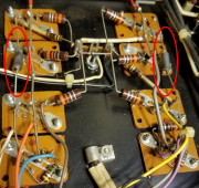
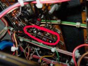
Here's another question: Can anybody tell me what the circled components are in the photo below? I think I figured out the rest of what I'm seeing.
Thanks!

Ferrite beads to tame high frequency parasitic oscillation
They are not shown on schematics
They are not shown on schematics
wattsabundant
Chief Journeyman
The 700B service manual mentions them in a bulletin that discusses oscillations.

