BGW 210 power amp

Michael F

Journeyman
Joined
Jul 3, 2013
Messages
394
Location
Montreal Canada
Tagline
---
#1
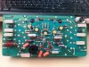
HI all, hopefully some one here can shed some light on a power amp that doesnt seem to like a load placed on it :(

With no load connected to the output, it will swing 36 vac with a clean waveform but as soon as you connect a load, the protection relay kicks in.

Backing down the input level to the point just before relay engagement, I see that the negative waveform is missing and the DC content is about 4 volts.

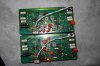
There are no visible signs of component failure and the DC offset is .005

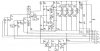
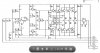
Unfortunately this seems to be a rare model, I cant find anything on it online but it does seem to be similar to the model 250, 100wpc class AB complimentary.

What should I be looking for?
TIA
 

laatsch55

Administrator,
Staff member
Joined
Jan 14, 2011
Messages
74,987
Location
Gillette, Wyo.
Tagline
Halfbiass...Electron Herder and Backass Woof
#2
What does it have for outputs?? And what does it have for input differential pairs??
 

laatsch55

Administrator,
Staff member
Joined
Jan 14, 2011
Messages
74,987
Location
Gillette, Wyo.
Tagline
Halfbiass...Electron Herder and Backass Woof
#5
It could be so many things Mike...Power supply OK under load? Predrivers OK? Protection circuit weak? It looks like a negative pre-driver problem, but that could be any component on the negative side. Does it do it in both channels??
 

laatsch55

Administrator,
Staff member
Joined
Jan 14, 2011
Messages
74,987
Location
Gillette, Wyo.
Tagline
Halfbiass...Electron Herder and Backass Woof
#7
Download the data sheet on the 318 to see what you are supposed to have on all pins, I'd start my search around the negative predrivers...
 

Michael F

Journeyman
Joined
Jul 3, 2013
Messages
394
Location
Montreal Canada
Tagline
---
#9
It could be so many things Mike...Power supply OK under load? Predrivers OK? Protection circuit weak? It looks like a negative pre-driver problem, but that could be any component on the negative side. Does it do it in both channels??
The power supply seems fine because the right channel performs properly.
 

laatsch55

Administrator,
Staff member
Joined
Jan 14, 2011
Messages
74,987
Location
Gillette, Wyo.
Tagline
Halfbiass...Electron Herder and Backass Woof
#10
It's probably some of those TO-39's....I found an owners manual with a schematic and parts list for the 250, is it similar in construction to the 210?

In the circuit description it says it has an SCR crowbar for load protection, see an SCR in there anywhere??
 

Michael F

Journeyman
Joined
Jul 3, 2013
Messages
394
Location
Montreal Canada
Tagline
---
#11
It's probably some of those TO-39's....I found an owners manual with a schematic and parts list for the 250, is it similar in construction to the 210?

In the circuit description it says it has an SCR crowbar for load protection, see an SCR in there anywhere??
Lee, you are likely looking at a very early model (I`d say pre `77) 250 where a crowbar circuit was used, all models used a big ass relay from that point on.
 

laatsch55

Administrator,
Staff member
Joined
Jan 14, 2011
Messages
74,987
Location
Gillette, Wyo.
Tagline
Halfbiass...Electron Herder and Backass Woof
#12
OK, but something has to trigger that relay, do you suppose the 250 schemo is comparable to the 210? Perhaps they stuck to the same design? I think Joe would have a better idea what's going on if the schemo is comparable. If the scope shows a good waveform up to a point, shit, it could be a resistor, cap, small transistor.etc. Ya may just have to test every component on the board...
 

Michael F

Journeyman
Joined
Jul 3, 2013
Messages
394
Location
Montreal Canada
Tagline
---
#13
This amp is a rare bird. My understanding is that it`s a home version of the model 250E, no balanced input options, banana speaker terminals, lighter gauge front panel.
It has a bigger sibling, a model 410 which is likely a scaled down 750B.

Take a look at the screen shot of a model 250 D and E
 

Attachments

laatsch55

Administrator,
Staff member
Joined
Jan 14, 2011
Messages
74,987
Location
Gillette, Wyo.
Tagline
Halfbiass...Electron Herder and Backass Woof
#14
The MJE 340 is the negative pre-driver, but there's a whole lotta stuff attached to it that can affect it. Take some voltage readings on all 3 of it's legs when the relay isn't tripped, and then with it tripped and see what ya got....
 

Michael F

Journeyman
Joined
Jul 3, 2013
Messages
394
Location
Montreal Canada
Tagline
---
#15
Please keep in mind the schematic is that of a model 250. The output sections appear to be similar but things are different upstream, notably 3 pre drive TO-225 MJE transistors compared to 5 TO-5 found on the model 210.

You say the MJE340 is the negative predriver, would that make the MJE350, Q1 the positive predriver? What role does Q2 MJE720 play?
 

Attachments

Gepetto

Administrator
Staff member
Joined
May 15, 2011
Messages
14,091
Location
Sterling, MA
Tagline
Old 'Arn Enthusiast
#17
Please keep in mind the schematic is that of a model 250. The output sections appear to be similar but things are different upstream, notably 3 pre drive TO-225 MJE transistors compared to 5 TO-5 found on the model 210.

You say the MJE340 is the negative predriver, would that make the MJE350, Q1 the positive predriver? What role does Q2 MJE720 play?
It sets the bias for the output stage.
 

Michael F

Journeyman
Joined
Jul 3, 2013
Messages
394
Location
Montreal Canada
Tagline
---
#18
Update

It turns out this amp is a later, fully comp version virtually identical to the model 410 who`s schematic is available :)
I tested all the semiconductors and resistors including the emitter resistors and everything checked out fine. Because this was done in-circuit, there were a couple of readings that didn't seem right but I used the working module as a reference for confirmation.

After reinstalling the module for further testing, it decided to work and well, putting out 128w into my 8 ohm load without breaking a sweat. Even though it isnt rated below 8, I dropped the load to 6 ohms where it put out 150w.
Why stop there, lets see what it does into 3 ohms. CLICK goes the protection relay, no more negative signal. Backing the input down to just below the relay engagement threshold, I gave the heatsink a few raps with my screwdriver and saw the negative waveform momentarily reappear. I then started poking around the PC board and was able to recreate the fault condition by applying a little pressure to the lower right corner of the PC board. Although there were no obvious cold joints or broken traces except for maybe the lone diode CR6, I just reflowed all the joints in that quadrant and that seemed to do the trick , does that sound plausible?
I`ve been cycling the amp at half power, one hour on, half hour off all evening and so far so good. It doesnt object to a 3 ohm load either where it puts out 161w.
I hope I`m not prematurely declaring victory but it would appear that the issue has been solved, thank you kind gentlemen for your input:)
 

Attachments

Top