When a 1Khz sine wave is injected into pin 6 of the meter board, pin 1 of Z301 remains at 7.0vdc and I get no reaction from the meter. If I boost the signal up a bit it eventually starts to flash the last 4 LEDs in the array only. When I jumper R320, the same thing occurs. Pin 1 of Z301 remain at 7vdc and the last 4 LEDs flash (no other LEDs react.)
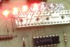
I also pulled all 6 led banks and tested them with a regulated power supply. Sure enough, 2 of the banks are bad..1 of the bad banks came from the board we are testing and it was located in the 1st bank. The 2nd and 3rd bank tested OK. On the board I was testing, I replaced all three sockets with known good LED panels and unfortunately got the same test results when all 3 panels test good.
At minimum, I need 2 LED panels. If there's a reasonable replacement, I'll replace all 6. Any sources?
I still have the issue at hand to deal with as well.