WHAT HAS WHITE OAK DONE NOW??????????????

laatsch55

Administrator,
Staff member
Joined
Jan 14, 2011
Messages
74,825
Location
Gillette, Wyo.
Tagline
Halfbiass...Electron Herder and Backass Woof
#1
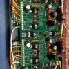
In response to the End-of-Lifing of several key components on the famous Rev "D" driver board, Joe set out to remedy this situation. Of course Joe never just "remedies" the situation, he surpasses his previous deeds well and spectacularly, this being one of those times. He has not only re-engineered the entire board, but has made it a better performer WITHOUT SACRIFICING that sound we love so well. Joe has had his 400 lab mule running for quite a bit longer than I have had the Pig running the new board....ahem....anyway....
I have had cable hell and some hiccups with the Pig, so we will be using Joe's measurements for all performance specs till i can correct some cable issues and get the Pig to behave. I will let Joe explain what he has done , but herein are some pics of the board construction and installation.

Fellas , I ind it amazing the degree of component change and the familiarity of the sound. There are some slight differences, the bass is tighter, faster, and better defined, the mids and highs remain pretty much the same.....EXCEPT for their abilty to handle....say....like some very loud flute passages on some Shpongle...which can at times drive me from the room or turn down the volume on the K's ( not my preferred option) are now doable at high volume. Overall impression is better overall defionition with a reduction in listener fatigue ( wasn't much to begin with) ......


Behold!! The Rev "E" driver board!!

Your baggage having thusly been carried you may proceed Joe!!


Attachments

laatsch55

Administrator,
Staff member
Joined
Jan 14, 2011
Messages
74,825
Location
Gillette, Wyo.
Tagline
Halfbiass...Electron Herder and Backass Woof
#4
Rest assured to those who have had amps built and guaranteed.....I have enough parts on hand to honor that guarantee.....should it ever be required....
 

gadget73

Journeyman
Joined
Aug 29, 2014
Messages
465
Tagline
---
#5
What parts were EOL, the TO-39 driver transistors ? Looks like I'm seeing a TO-220 transistor in the spots where the roundies used to be.


Very cool stuff though.
 

NavLinear

Veteran and General Yakker
Joined
Apr 12, 2012
Messages
6,056
Location
SoCal
#6
This is a very nice looking layout. I like that the germanium transistors are history along with the other transistors in a can. I like the addition of the heat sinks for the new transistors. I love it! Fantastic job Joe and nice build Lee.

That dc offset is in the mud - does this mean you figured out the problem you're having with the Pig?
 

laatsch55

Administrator,
Staff member
Joined
Jan 14, 2011
Messages
74,825
Location
Gillette, Wyo.
Tagline
Halfbiass...Electron Herder and Backass Woof
#7
What parts were EOL, the TO-39 driver transistors ? Looks like I'm seeing a TO-220 transistor in the spots where the roundies used to be.


Very cool stuff though.

Yep, that and some of the TO-92's were in danger of being in turmoil ....
 

Gepetto

Administrator
Staff member
Joined
May 15, 2011
Messages
13,944
Location
Sterling, MA
Tagline
Old 'Arn Enthusiast
#8
What parts were EOL, the TO-39 driver transistors ? Looks like I'm seeing a TO-220 transistor in the spots where the roundies used to be.


Very cool stuff though.
Release Notes for the RevE PL14_20 Control Board


  1. Changed the Q7 and Q10 from ST Micro 2N5416 and 2N3439 (used on RevA, C and D) to ON Semi MJE15035 and MJE15034 respectively. While the 2N5416 and 2N3439 are excellent devices, they have gone end of life from ST Microelectronics, the last standing manufacturer of these devices. The new ON Semi devices are more rugged, have wider GBW, more consistent beta, higher Ft (15MHz to 30MHz), higher power rating (2W vs. 1W) and larger and rated SOA. The package has converted to TO-220 from TO-5. The heat sinks used with TO-220 are also more commonly available. Each device is bolted down making the mounting more rugged as well. The new reference locations are Q9 and Q6 respectively due to renumbering of the entire board.
  2. Changed Q5 from ST Micro 2N3439 to a triplet of ON Semi MPSA42 devices, again for end of life reasons only. The MPSA42 devices are multi sourced from ON Semi, Fairchild Semiconductor, Central Semi and MCC. The Ft of the MPSA42 is >50MHz versus >15MHz for the 2N3439, more than triple that of the original transistor while operating at an equal or greater beta. The new reference locations are Q3, Q4 and Q5 respectively due to renumbering of the entire board.
  3. Changed the MPSA18 long tailed pair that formed the initial gain stage to a single 8 pin OPA134 Burr Brown audio OP Amp to increase the gain of the initial gain stage allowing a wider, flat high frequency response. This also improves the amplifier offset voltage which will typically be 0.000 to +/- 0.001V after this change. Prior offset was typically in the range of -0.009 to -0.012V due to the bias current of the MPSA18 NPN gain stage. The OP Amp may be socketed allowing the alternate, potential use of the OPA627 or LME49710 amplifiers as well. Future results will be determined with these OP Amps.
  4. Provided additional power supply bypassing for the power rails of supplying the OP Amp voltages to improve further on PSRR of the board assembly.
  5. Changed the -3dB point of the input filter from 166KHz to 83KHz by changing the filter capacitor from 120pF to 240pF.
  6. Retained the MPSA92 current mirror/level shifting circuit from the RevD assembly and added local, intermediate bypassing to further improve on PSRR characteristics of the board. Rescaled the values used in the current mirror to reduce the gain of this stage to better balance the work done by this stage and the front end OP Amp. Reduced the impedance of the output of this stage to push the effect of Cob of the MPSA42 triplet to >45MHz, well out of the amp bandwidth to further improve phase margin for the amp.
  7. Changed the +/- regulated bias supplies from +/- 20VDC to +/- 15VDC to satisfy the requirements of the OP Amp used in the front end. Rescaled other components that relied on these rail voltages appropriately. Added more bypass capacitors on these rails in critical circuit areas.
  8. Added test points for +15V, -15V and GND to allow these regulated voltages to be easily checked.
  9. Changed the amplifier SOA protection circuit topology that relied on 2N1304 and 2N1305 Germanium transistors to enable the use of high performance silicon devices instead. This eliminates another end of life component situation as the original Germanium transistors were becoming extremely scarce and hard to find. While the 2N1304 and 2N1305 devices are excellent devices for this application, the substitute silicon parts are even more rugged. NOTE WELL: When used in PL400 amplifiers, the output device emitter resistors must be changed from 0.22 ohm resistors to 0.33 ohm resistors for proper operation.
  10. Added a fourth series diode location in the Bias Transistor location to allow better bias adjustment control for full complementary configurations. In Full Comp mode, D1-D4 are populated. In Quasi Comp mode, D1-D3 are populated and D4 is populated with a 1 ohm jumper resistor.
  11. Change lead spacing for C6L, C6R, C8L, C8R, C9L, C9R, C14L, C14R, C15L and C15R to more appropriately match the 0.234†spacing on mica CM05/CD15 type capacitors.
  12. Enlarge pads on all mica and film caps to improve board durability.
  13. Move components farther away from Q6 bias transistor connections to allow installation of the Phoenix Contact connector on the back side without hitting other pads or interfering with the cross wire or coming close to adjacent components.
  14. Provide connection from Q2L/R collector through R10L/R to the B- rail to improve the symmetric current drain on the B+/B- rails. This improves power supply load symmetry and ensures that both supplies power on and decay at very similar rates, improving turn on and off control.
  15. Increase the value of C8L/R and C9L/R to improve stability of the bias voltage during active operation. C8L, C8R, C9L, C9R to 0.15uF/100V. Slows down the bias changes with change in output signal level, making the bias current more consistent with loading.
  16. Increase the value of C5L/R to better offset the ESR of C4 (was C6 in RevD artwork) and provide more consistent and flat response at higher frequencies. C5L and C5R to 1uF/63V. Improves the frequency response flatness by doing a better job countering the ESR of C6.
  17. Retained all of the RevD board size and mounting hole attributes.
  18. Retained all of the RevD locations for all of the Phoenix Contact connectors to preserve full mechanical compatibility with RevD boards.
  19. Retained the lower edge I/O PNPL/R pads to allow use of the RevE board to replace the original PL36 board version in the fully complementary versions of the PL400/PL700 Series 2 amplifier (the last PL36 board artwork added these extra pins). Resistor options and wiring options enable the RevE board to be used in this application.
  20. Split function of the C9L/R local feedback capacitor (was originally C5L/R, 120pF on RevD and earlier boards) into 2 capacitor values. Added C8L/R as lead network across R13L/R (was originally R15L/R on RevD and earlier boards) in the global feedback path. C9L/R value at 56pF to allow increased gain bandwidth of OPA134 stage for reduced distortion and C8L/R value at 62pF.
  21. Added C14L/R as Miller capacitors across the collector-base junction of Q3-5L/R to tailor/optimize the gain bandwidth and slew rate of Q3-5L/R. Populate C14L/R at 120pF. Depopulated C15L/R (was originally C7L/R, 180pF on RevD and earlier boards)
  22. Changed the value of R9L/R to provide better centering of the bias timmer on most amps. R9L/R from 270 (or 2.49K for Full Comp) ohms. Improves the adjustability of the bias pot in most amps.
  23. Added R39L/R in series with the collector of Q9L/R to provision for RevE board use in the Full Complementary configuration.
  24. Renumbered all components starting at upper left corner progressing left to right to lower right corner in order to make it easier to locate components on the new artwork. Since the new circuit bears little resemblance to the original PL circuit, it made little sense to retain the original reference designators.
  25. Overall, improved upon the already high quality of the RevD board in the creation of the RevE artwork by making small moves of components to improve assembly clearances, shorten and widen traces, increase trace clearances and improve signal integrity to maximize audio quality.
  26. Overall weight (mass) changed to 188 grams with the Phoenix Contact Connectors installed versus 186 grams for the RevD board assembly.


005.jpg
 

laatsch55

Administrator,
Staff member
Joined
Jan 14, 2011
Messages
74,825
Location
Gillette, Wyo.
Tagline
Halfbiass...Electron Herder and Backass Woof
#9
This is a very nice looking layout. I like that the germanium transistors are history along with the other transistors in a can. I like the addition of the heat sinks for the new transistors. I love it! Fantastic job Joe and nice build Lee.

That dc offset is in the mud - does this mean you figured out the problem you're having with the Pig?
No Navo, the Pig...being true to form has not gone quietly with the new board., I think he was partial to his old one.... on initial power up--exceptional offset and bias behavior. But when checking residual noise I had 9 MILLIVOLTS, now that just ain't right NEVER ON MY WORST DAY has it been over 1.25 MILLIVOLTS....drove me nuts till Joe said refer to rule 1---check test equipment...well to some degree that was correct but my Fluke 179 backed up what the AP was seeing. Joe called for a small adjustment of removing one resistor and replacing with a jumper. residual dropped to less than 2MV. Now, keep in mind Joe was not having these problems , his build progressed with exceptional results, mine has continously otten better but aftyer that initial adjustment i have been all over the place chasing electron ghosts....so i said F&^%$ it and put it on the horns. A black hole for noise----again---- and I can not correlate my measurements with what I DON"T hear.....so goes the saga....will keep everyone up to date on this anomily... it's certainly not the board, but rather the implementation on my part. Although I can't hear anything wrong....
 

laatsch55

Administrator,
Staff member
Joined
Jan 14, 2011
Messages
74,825
Location
Gillette, Wyo.
Tagline
Halfbiass...Electron Herder and Backass Woof
#10
Changed the amplifier SOA protection circuit topology that relied on 2N1304 and 2N1305 Germanium transistors to enable the use of high performance silicon devices instead. This eliminates another end of life component situation as the original Germanium transistors were becoming extremely scarce and hard to find. While the 2N1304 and 2N1305 devices are excellent devices for this application, the substitute silicon parts are even more rugged. NOTE WELL: When used in PL400 amplifiers, the output device emitter resistors must be changed from 0.22 ohm resistors to 0.33 ohm resistors for proper operation.


OH GOID!!! I am soooooooooooo dense some times....Joe....I'm still running the .22ohmers...jeez....
 

Gepetto

Administrator
Staff member
Joined
May 15, 2011
Messages
13,944
Location
Sterling, MA
Tagline
Old 'Arn Enthusiast
#11
In response to the End-of-Lifing of several key components on the famous Rev "D" driver board, Joe set out to remedy this situation. Of course Joe never just "remedies" the situation, he surpasses his previous deeds well and spectacularly, this being one of those times. He has not only re-engineered the entire board, but has made it a better performer WITHOUT SACRIFICING that sound we love so well. Joe has had his 400 lab mule running for quite a bit longer than I have had the Pig running the new board....ahem....anyway....
I have had cable hell and some hiccups with the Pig, so we will be using Joe's measurements for all performance specs till i can correct some cable issues and get the Pig to behave. I will let Joe explain what he has done , but herein are some pics of the board construction and installation.

Fellas , I ind it amazing the degree of component change and the familiarity of the sound. There are some slight differences, the bass is tighter, faster, and better defined, the mids and highs remain pretty much the same.....EXCEPT for their abilty to handle....say....like some very loud flute passages on some Shpongle...which can at times drive me from the room or turn down the volume on the K's ( not my preferred option) are now doable at high volume. Overall impression is better overall defionition with a reduction in listener fatigue ( wasn't much to begin with) ......


Behold!! The Rev "E" driver board!!

Your baggage having thusly been carried you may proceed Joe!!

Lee provides quite the introduction :). And thank you very much kind sir.

We worked hard to keep the sound of the PL with the RevD while extending the clean frequency response out past 80KHz with distortion levels below 0.06% even at wattages as low as 10W out. The background of the RevD board was quite black but the RevE background is even blacker and we are seeing SNR in excess of 101 dB. That makes the dynamic range of the music have even more impact.


It took a motivator like ST Micro dropping the famous 2N3439 and 2N5416 hard to make this happen since the RevD board was so good. And they dropped them hard. Distributor inventory dried up overnight when customers found out they were exiting this business. Like Lee, I have retained a healthy buffer inventory but "it was time."

While the RevE looks quite different within the boundaries of the board, all the pin numbering and locations have remained exactly identical to the RevD including the overall size and mounting locations.

Lee corroborated the results I measured with the HP8903B with his AP so we feel good about the performance results.

Listening experience:

Piano sounds great with a soft edge. Standing bass is more pronounced and defined, bass overall is well defined and solid. Vocals are slightly clearer but not strident. The OPA134 is a great Burr Brown device and creates a great musical experience. The background is absolutely black...
 

Gepetto

Administrator
Staff member
Joined
May 15, 2011
Messages
13,944
Location
Sterling, MA
Tagline
Old 'Arn Enthusiast
#12
Changed the amplifier SOA protection circuit topology that relied on 2N1304 and 2N1305 Germanium transistors to enable the use of high performance silicon devices instead. This eliminates another end of life component situation as the original Germanium transistors were becoming extremely scarce and hard to find. While the 2N1304 and 2N1305 devices are excellent devices for this application, the substitute silicon parts are even more rugged. NOTE WELL: When used in PL400 amplifiers, the output device emitter resistors must be changed from 0.22 ohm resistors to 0.33 ohm resistors for proper operation.


OH GOID!!! I am soooooooooooo dense some times....Joe....I'm still running the .22ohmers...jeez....
That only matters if you really want that to kick in Lee. With MJ21195 and 96 devices, the SOA capability is so superior to the old PL909 devices that it does not really matter much.

That note is there for completeness...
 

laatsch55

Administrator,
Staff member
Joined
Jan 14, 2011
Messages
74,825
Location
Gillette, Wyo.
Tagline
Halfbiass...Electron Herder and Backass Woof
#14
Amen on the 3439's and 5416's drying up overnight. After a day and a half of e-mailing back and forth over how many thousands we were going to buy.....they were gone....
 

Gepetto

Administrator
Staff member
Joined
May 15, 2011
Messages
13,944
Location
Sterling, MA
Tagline
Old 'Arn Enthusiast
#15
Not running 95's and 96's in the Pig, but 93's and 94's.....
Those are 'almost' as good in the SOA department Lee. I think you have blown up just about everything in the Pig over time but I don't recall you blowing any of the primary output devices.
 

Gepetto

Administrator
Staff member
Joined
May 15, 2011
Messages
13,944
Location
Sterling, MA
Tagline
Old 'Arn Enthusiast
#16
Amen on the 3439's and 5416's drying up overnight. After a day and a half of e-mailing back and forth over how many thousands we were going to buy.....they were gone....
Like .22 ammo at Walmart, gone before it even hits the shelf...
 

laatsch55

Administrator,
Staff member
Joined
Jan 14, 2011
Messages
74,825
Location
Gillette, Wyo.
Tagline
Halfbiass...Electron Herder and Backass Woof
#17
Those are 'almost' as good in the SOA department Lee. I think you have blown up just about everything in the Pig over time but I don't recall you blowing any of the primary output devices.
Not since the backplane installation.......I have carelessly roasted some outputs in previous iterations prior to the backplanes...I'll have you know ICAN blow up anything!!
 

laatsch55

Administrator,
Staff member
Joined
Jan 14, 2011
Messages
74,825
Location
Gillette, Wyo.
Tagline
Halfbiass...Electron Herder and Backass Woof
#18
Like .22 ammo at Walmart, gone before it even hits the shelf...

That was a shocker....I thought we had a month or so to get our duck in a row. Must have been some pretty good sized outfits depended on them....
 

Gepetto

Administrator
Staff member
Joined
May 15, 2011
Messages
13,944
Location
Sterling, MA
Tagline
Old 'Arn Enthusiast
#19
That was a shocker....I thought we had a month or so to get our duck in a row. Must have been some pretty good sized outfits depended on them....
Yes, while we are a reasonable 'user' there were many big companies scrambling after that bombshell hit that still had them in their legacy designs. It would not surprise me to see some company spring up with the masks from ST and reentering the market. But that is 'so 2014' for us right now. :)
 

laatsch55

Administrator,
Staff member
Joined
Jan 14, 2011
Messages
74,825
Location
Gillette, Wyo.
Tagline
Halfbiass...Electron Herder and Backass Woof
#20
Notice those two specs there fellas....distortion...throughout the entire band is POINT 06%

When previously we had some test as high as POINT 275 % in certain frequencies...


SNR of 101db is world class in a 400. that translates to a BUNCH in a 700....Joe could do the math for ya fellas...


And another benefit of all this......the sound difference between the 700 and 400 shrinks even more...residuals are in the basement anyway...

 
Top