Kev's "Cobble Together a Good 3000 PL Preamp" thread...

kevin

Forum Veteran and Hillbilly
Joined
Dec 22, 2011
Messages
1,422
Location
Wise VA
#81
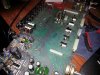
Yep, I see a few TIS's there - those are the relay current sinks.

Hey.. look carefully... on the bottom right look at the cluster of 4 caps with two DIP-8's on either side. Look at those two resistors that look "new", but you can see they both burnt up at one time with the discoloration around 'em. Hmm.. that's the headphone amp, I believe. Better test it out if Kev is going to use a pair of cans..
Don't even own a pair Jer !!!
 

kevin

Forum Veteran and Hillbilly
Joined
Dec 22, 2011
Messages
1,422
Location
Wise VA
#83
I'd say all I will ever run through that thing is a CD player and maybe a I-pod !!
 

Gepetto

Administrator
Staff member
Joined
May 15, 2011
Messages
14,098
Location
Sterling, MA
Tagline
Old 'Arn Enthusiast
#85
Old ones.. 1K
New .. 270

Hmmmmm... might be just a little too much current? I do still have those heavy duty guys, but at least with them the coil is around 780 ohms. They are 18 volt as well..

Jer
Measure the unregulated input voltage to the positive regulator, that is the output of the diode bridge and let us know what that is?
 

jbeckva

Admin/Server Dude MAA Guy
Staff member
Joined
Jun 11, 2010
Messages
6,853
Location
Powhatan, Virginia, United States
Tagline
WassupYa Mang?
#88
Sure on your schedule Jer...
Just thinking strongly that I am going to use those other relays, Joe. They too have gold contacts rated at 20 million operations during the lifetime of the relay, and right at the 18 volt coil rating they are a lot closer to what I am going to dial the voltage in at .. probably 17 volts.. maybe 16... And a lot closer to the originals, coil current wise.

(Kev - just don't freak out when it sounds like a "substation" when you're changing the inputs.. heheh...) :happy7:
 

jbeckva

Admin/Server Dude MAA Guy
Staff member
Joined
Jun 11, 2010
Messages
6,853
Location
Powhatan, Virginia, United States
Tagline
WassupYa Mang?
#92
One more mod needed...

The main output relay normally is "time delayed" via a transistor switch, where it's base is hooked to a cap that charges. In the bias circuit for it, however, is a 15 volt zener that would "drop" the normally 20 volts down to about 5 to provide the charging voltage. Since I'm 3 volts down now tho, that five volts now becomes 2 volts... which apparently isn't enough to kick the transistor to fully conduct (I'm getting about 7 volts on the collector when I should be getting less than 1).

Sooo.. that 15 volt zener needs to also go down 3 volts, to a 12 volt one. Hmmm... wish I could find a 12 volt zener laying around (I imagine if I look hard enough...). Otherwise time for a mouser order again... bummer!

It's interesting tho - my own 3000 kicks the relay fine. I think I just lucked out there, because the preamp board before this I had the same issue. I just "solved" it a little bit on the unorthodox side (don't ask.. it didn't quite work out there... heheh).

Here's the circuit....

outputckt.jpg
 

laatsch55

Administrator,
Staff member
Joined
Jan 14, 2011
Messages
75,030
Location
Gillette, Wyo.
Tagline
Halfbiass...Electron Herder and Backass Woof
#93
The 3300 has a solid state relay consisting of 2 tranny's, couple caps and resistors...
 

jbeckva

Admin/Server Dude MAA Guy
Staff member
Joined
Jun 11, 2010
Messages
6,853
Location
Powhatan, Virginia, United States
Tagline
WassupYa Mang?
#95
So ya got 2 in's and one out??
2 in's (Aux and Tuner), and 2 outs... the relay that is normally next to the one on the end (K13) is the one that would disconnect the "switched" preamp out when a pair of headphones is plugged in. I went ahead and bypassed it, so K13's switched output (k13 is that time delay startup relay) is hardwired to both preamp outs now.

I'm just thinking... I COULD bug up the 3 relays needed for the phono section, as that too was recapped and probably sounds pretty good... hmmmm... but heck if Kev's not going to use it, then that would be work wasted. Yeah I know, brand new caps sitting idle... but I did that anyway for the "look" heheh.
 

jbeckva

Admin/Server Dude MAA Guy
Staff member
Joined
Jun 11, 2010
Messages
6,853
Location
Powhatan, Virginia, United States
Tagline
WassupYa Mang?
#96
You need 5 on the base to turn it on??
5 volts on the left side of that 51K resistor, apparently... the zener's going to drop 15 from whatever the rail voltage is at the time (20 volts before, now 17.. lil less than 17). So figure the south end of the zener SHOULD be around 5 volts, feeding into the bias/cap charging circuit for the transistor.
 

CASSETTE DECK

Chief Journeyman
Joined
Jun 20, 2013
Messages
696
Location
Kapiti Coast, New Zealand
Tagline
Path under Coastlands overbridge
#99
The main output relay normally is "time delayed" via a transistor switch, where it's base is hooked to a cap that charges. In the bias circuit for it, however, is a 15 volt zener that would "drop" the normally 20 volts down to about 5 to provide the charging voltage. Since I'm 3 volts down now tho, that five volts now becomes 2 volts... which apparently isn't enough to kick the transistor to fully conduct (I'm getting about 7 volts on the collector when I should be getting less than 1).

Sooo.. that 15 volt zener needs to also go down 3 volts, to a 12 volt one. Hmmm... wish I could find a 12 volt zener laying around (I imagine if I look hard enough...). Otherwise time for a mouser order again... bummer!

It's interesting tho - my own 3000 kicks the relay fine. I think I just lucked out there, because the preamp board before this I had the same issue. I just "solved" it a little bit on the unorthodox side (don't ask.. it didn't quite work out there... heheh).

Here's the circuit....

View attachment 13597
I have a variant of this circuit that has a 5.6 volt zener diode on the base of the relay driver transistor instead of a zener diode on the time delay capacitor charging circuit.

DSC00030.jpg

Resistor values not specified in schematic. Dependent on supply voltage and time delay required.
Decoupling capacitors not shown in schematic.
 
Last edited:
Top