Hey Everyone,
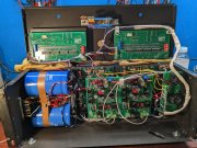
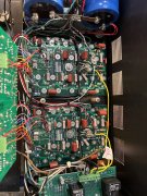
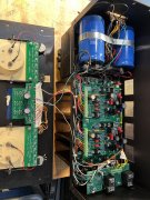
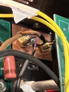
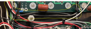
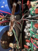
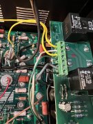
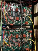
I have been battling this newly rebuilt 700B for a while now and it's driving me crazy!! Everything had been great, from the new backplane, control pcb, chassis, etc.. Bias has always been good and it sounds great except for some low level buzz on the left channel. I have recently disconnected the DC to chassis gnd connection at the left backplane and thought that disconnecting it helped but alas it didnt. So now I'm back to where I started....copper buss at inputs, no mode switch, bypassed volume pots, star ground wiring. Even with the input coax disconnected from the control board the channel still buzzes. And when I have it open I can place my hand over the left channel of the control board and effect the buzz (I am obviously acting as a shield from some interference). Any thoughts or suggestions of what to check next? One more thing, I even tried a new control board and have the same issue. Thanks so much!!
Jeff

") You can get over 108dB SNR if you are very careful with wire routing.
You can get over 108dB SNR if you are very careful with wire routing.