Starting WOPL 400 Finally!

timmydawg

New Around These Parts
Joined
Apr 26, 2021
Messages
19
#1
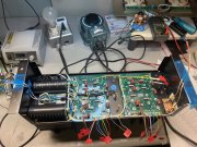
Ready to get this 400 up and running, This is my first WOPL so it seemed to take forever to read, research and try to understand what I am doing. I have tried to emulate what others have done and I appreciate the fine craftsmanship that I am attempting to copy. I tested for shorts to chassis so I am on to step # 12, Wish me luck !
IMG_1799.JPG
 

timmydawg

New Around These Parts
Joined
Apr 26, 2021
Messages
19
#2
Voltage check B+ 80V, B- 80v , now on to the bottom row of transistors.
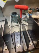
Does anyone use the 10" T handle Allen wrench? It seems like the length keeps me from applying to much torque on the bolts, hopefully just the right amount. I was having problems with the lamp socket on my Dim bulb tester, I will have to change that out before continuing. IMG_1801.JPG
 

WOPL Sniffer

Veteran and General Yakker
Joined
Aug 10, 2015
Messages
11,478
Location
Minnie-Soda
Tagline
Screw it
#3
Voltage check B+ 80V, B- 80v , now on to the bottom row of transistors.
Does anyone use the 10" T handle Allen wrench? It seems like the length keeps me from applying to much torque on the bolts, hopefully just the right amount. I was having problems with the lamp socket on my Dim bulb tester, I will have to change that out before continuing. View attachment 83058


Even at 5-6 inch Lbs that T-handle can still be too much.
 

timmydawg

New Around These Parts
Joined
Apr 26, 2021
Messages
19
#4
I found that out the hard way yesterday, installed the bottom row and as I applied voltage the dim bulb was not dimming . I pulled the transistors back out and noticed one of the Sil pads had been cut right on the rhombus ,so today I will be smoothing the edges and installing with a much lighter touch.
 

George S.

Veteran and General Yakker
Joined
Feb 18, 2020
Messages
4,916
#5
Couple points
A very fine touch is needed when snugging up the output screws.
To facilitate this, I run a sharp tap though the soldered in nuts to chase the threads after soldering.. And, I very lightly grease the threads of the screws.
I want the threads clean and very lightly lubricated.
We'd like to think that that outputs are perfectly flat to a thousand inch, but they're not.
So, slowly and evenly snug them down until the siil-pad begins to curl or wrinkle on the protruding edge, then stop,
I get my eyes as close as possible, and use a magnifying headset to precisely do this.
A T-handle is very capable of over tightening the screws and making the outputs even less flat .
A very fine touch is needed.
I cut the tip off a old Phillips screwdriver, drilled and pressed a Allen key shank into the end of it
 

WOPL Sniffer

Veteran and General Yakker
Joined
Aug 10, 2015
Messages
11,478
Location
Minnie-Soda
Tagline
Screw it
#6
I found that out the hard way yesterday, installed the bottom row and as I applied voltage the dim bulb was not dimming . I pulled the transistors back out and noticed one of the Sil pads had been cut right on the rhombus ,so today I will be smoothing the edges and installing with a much lighter touch.

Draw them down evenly too. I've never had to smooth the edges of an output (and I've done a bunch).
 

timmydawg

New Around These Parts
Joined
Apr 26, 2021
Messages
19
#7
George & Sniff,
Thank you,
I did catch your suggestion on running a tap through the Pem nuts as I was finishing up on the boards,
and was quite surprised at the amount of metal shavings that it produced. I totally forgot to lube the threads, definitely my bad on that.
And drawing them down evenly just like torqueing down a head is an important part of the process as well.
I guess I was so concerned about the bring up procedure not having much electronics background that I whiffed on the mechanical aspect which should be one of my strengths.
Since I used a Dim bulb should the outputs still be good? I checked them on my meter with the diode function & hopefully that's how to test them they seemed to have comparable values .
 

timmydawg

New Around These Parts
Joined
Apr 26, 2021
Messages
19
#18
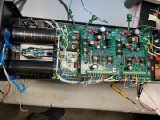
Back at it today, I wired up the control board , checked voltages , set bias and everything seems good but when I powered down and was going to discharge the bulk caps they were all ready discharged. WTF - I noticed that I had not hooked up the ground so I tried again and checked voltages on the caps and they were about 77.5V at 120V AC . And as soon as I turned power off the bulk caps immediately discharged down to about 1.5 V
Is this normal or is something wonky going on???
 

Attachments

Hexis22

Chief Journeyman
Joined
Dec 28, 2022
Messages
636
Location
Wisconsin
#19
Back at it today, I wired up the control board , checked voltages , set bias and everything seems good but when I powered down and was going to discharge the bulk caps they were all ready discharged. WTF - I noticed that I had not hooked up the ground so I tried again and checked voltages on the caps and they were about 77.5V at 120V AC . And as soon as I turned power off the bulk caps immediately discharged down to about 1.5 V
Is this normal or is something wonky going on???
Typical for the voltage to decay once the amp is assembled.

The control board linear regulators provide a load and discharge the main bulk caps, along with output bias current.
 
Top