Starting reassembly of my PL400II

Jess

New Around These Parts
Joined
Apr 28, 2019
Messages
27
Location
Placerville, CA
#1
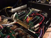
Howdy! I've just started reassembly of my PL400II. This has been a long project. I ordered my Backplane kit back in August of 2018. I grabbed the Control Board several months later, followed by the caps and I just got my output relay from WA a few weeks ago. The short version of why it's taken so long is I've been assembling the boards with my cousin when I'd visit him. Also, I didn't have a preamp lol. I just scored a PL4000I so I'm much more motivated to get this finished.

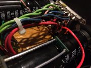
Anyway, in the assembly notes for the Backplanes it says to splice some 18AWG wire onto the white wire coming from the transformer to the thermal cutout. My PL400 has two wires coming from it that both look like 18AWG. Is it fine to splice them together into a single 18AWG or should run them separately? I'm probably overthinking this but since it's AC I didn't want to risk anything.

IMG_20191030_205651.jpg

Thanks very much!
 

mlucitt

Veteran and General Yakker
Joined
Jun 24, 2011
Messages
3,339
Location
Jacksonville, FL
#2
Jess, just one wire is all that is needed. The wire from the transformer primary to the thermal cutout originally ran through the center of the amplifier chassis, we re-route it up along the top to reduce the likelihood of AC hum into the circuit boards. When it is re-routed it is too short, so you need to lengthen it a bit. The instructions say to splice and insulate the connection of a length of black 18AWG wire to the transformer primary, then route it along the transformer casting and then to the left and counterclockwise around the AC 8 Amp fuse holder. This is the one that went from the transformer to the thermal cutout before you cut it. Don't know why you have two wires on that lug of the thermal cutout.
 

WOPL Sniffer

Veteran and General Yakker
Joined
Aug 10, 2015
Messages
11,223
Location
Minnie-Soda
Tagline
Screw it
#3
reminds me of the wiring for a 220V Transformer. Just like on the 700 Series II. 2 wires, Blue and Brown striped on one tab, and the Blue and Brown non-striped wires on the other. Paired together they are 120, split, they are 220
 

Jess

New Around These Parts
Joined
Apr 28, 2019
Messages
27
Location
Placerville, CA
#4
The wire from the transformer primary to the thermal cutout originally ran through the center of the amplifier chassis, we re-route it up along the top to reduce the likelihood of AC hum into the circuit boards. When it is re-routed it is too short, so you need to lengthen it a bit.
Yeah, this was all very clear to me. It's just that I have two wires from the transformer primary to the thermal cutout instead of one and I'm not sure if it's ok to solder the two wires together and add a single 18AWG wire to lengthen it or if I need to increase the gauge or use two wires. Sorry, does that make sense?

Thanks, Jess

IMG_20191031_195836.jpg
 

laatsch55

Administrator,
Staff member
Joined
Jan 14, 2011
Messages
74,126
Location
Gillette, Wyo.
Tagline
Halfbiass...Electron Herder and Backass Woof
#7
Yeah, this was all very clear to me. It's just that I have two wires from the transformer primary to the thermal cutout instead of one and I'm not sure if it's ok to solder the two wires together and add a single 18AWG wire to lengthen it or if I need to increase the gauge or use two wires. Sorry, does that make sense?

Thanks, Jess

View attachment 37693
Yes, that makes sense Jess. On the AC in, one goes to the transformer, the other goes to the thermoswitch then back to the other primary tap on the transformer. Cant remember which leg of the AC in goes through the mains fuse .
 

mlucitt

Veteran and General Yakker
Joined
Jun 24, 2011
Messages
3,339
Location
Jacksonville, FL
#8
Yeah, this was all very clear to me. It's just that I have two wires from the transformer primary to the thermal cutout instead of one and I'm not sure if it's ok to solder the two wires together and add a single 18AWG wire to lengthen it or if I need to increase the gauge or use two wires. Sorry, does that make sense?

Thanks, Jess

View attachment 37693
Jess, your second picture explains your situation better than the closeup of the thermoswitch. It looks like you have a PL 400 II that is using a 120/220 primary (international) transformer. See the drawing below. Joe can confirm this, I have never personally had one of these. The drawing shows how both pairs of windings are brought out and connected together for 120V or they are linked in the middle and only two wires come out for 240V operation. It is safe to connect both of those loose wires together and then run one wire from that connection to the thermoswitch. Ignore the voltages listed for the secondaries in the drawing.

trans61.gif
 

Jess

New Around These Parts
Joined
Apr 28, 2019
Messages
27
Location
Placerville, CA
#9
The drawing shows how both pairs of windings are brought out and connected together for 120V or they are linked in the middle and only two wires come out for 240V operation. It is safe to connect both of those loose wires together and then run one wire from that connection to the thermoswitch.
Thanks very much! Sorry my first picture wasn't very clear.
 

mlucitt

Veteran and General Yakker
Joined
Jun 24, 2011
Messages
3,339
Location
Jacksonville, FL
#10
I would run a quick check of the transformer output voltages after the primaries are tied together on 120V. You should get +75-80V and -75-80V on the secondaries.
 
Top