Power switch mod?

Joined
Aug 27, 2022
Messages
122
Location
Ste. Genevieve, MO
#41
You talking about that Kenwood KR-9600 thread over at Audiokarma? I read through that whole thread when I restored my 9600. They showed how to do the triac trick. That was the only part of that thread I didn't do. Knowing I was selling it at the time I said fuck it. No need going any further. That was one bad ass unit.
Honestly don't recall.


Wanted to go back to it and can't find it now. Don was involved in it quite a bit.
 
Joined
Aug 27, 2022
Messages
122
Location
Ste. Genevieve, MO
#46
I developed a triac board for the 700's that is controlled by the original power switch. The goal was to preserve the original power switch in the 700B's which are near unobtanium. In the development process I captured a lot of inrush currents at turn on. Typical peak current during the first cycle was 100-125 amps. The highest recorded current was just shy of 150 amps. Downside? The triac has about a 1 volt drop across it which reduces output power at least a couple watts. Upside? never worry about failed power switch.
Hi Don, is your triac mod compatible with the PL-400 and if so, how do I get one?
 

wattsabundant

Chief Journeyman
Joined
Apr 26, 2011
Messages
842
Location
Central Ohio
#47
Well, yes, to a certain degree. The stock 400 doesn't have a power switch. The board was intended for the 700 that has a power switch. That switch is is subject to failure. The board does the actual power switching. It uses the existing switch on the 700 to control a solidstate triac that provides power to the amp. To use the board in a 400, the front panel of a 400 has to be drilled to accept a power switch of the users liking.

So why all the fuss? Both the 700 and 400 have a high power "in rush" when the switch is turned on. Many switches will weld the contact.

I hope this helps
 

mlucitt

Veteran and General Yakker
Joined
Jun 24, 2011
Messages
3,339
Location
Jacksonville, FL
#48
Don, do you mount your Triac Board with the back of the Triac against the PL chassis? Does the Triac even get hot running at 40 Watts of power dissipation?
You should explain to people that the Triac you selected is actually an Alternistor Triac - effectively two Thyristors (SCRs) wired inverse parallel (back-to-back) on the chip, which is specifically designed to switch heavy inductive loads and provides better turn off behavior than a standard Triac.
Also, the TO-218AC configuration of the Q4040K7 device will conduct 40 Amps when the amp is ON, will block a minimum of 400VAC when the amp is off, and can handle a maximum of 400 Amps "in-rush" surge for one cycle at power ON in the PL700B/PL700 II.
Finally, the metal mounting tab is electrically isolated from the device, so it can be attached directly to the chassis.

You picked a good device for this application.
 

wattsabundant

Chief Journeyman
Joined
Apr 26, 2011
Messages
842
Location
Central Ohio
#49
Well Mark, I think you said it for me.

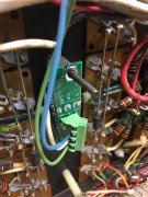
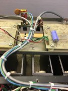
I call it a triac board as that is a term that many people recognize. Yes the triac mounts on the back of the board with the Phoenix connector on the top of the board. I use a 45 degree Phoenix connector to make it easier to land the wires. I don't remember the exact temperature rise of the triac at continuous full load. It was negligible. There are a few options for the location of the assembly. The install instructions use the top screw for the driver board along with suitable spacers and hardware. That simplifies the installation as the original switch wires are long enough to land on the triac board. Another option that would require drilling would be on the left side near the caps.

The thermal sensors could be rewired so that they are in the control loop for the triac. It would be pertinent if there was a history of sensor failures due to the high load current in them. I've yet to see one fail. If the sensor contact should weld, no one would know the difference.

I've got a new board that accommodates a TO220 package as well as TO218. Having a hard time moving forward with it. Weather in Ohio has been so gorgeous I hate to come in the house.
 

Attachments

mlucitt

Veteran and General Yakker
Joined
Jun 24, 2011
Messages
3,339
Location
Jacksonville, FL
#50
The thermal sensors could be rewired so that they are in the control loop for the triac. It would be pertinent if there was a history of sensor failures due to the high load current in them. I've yet to see one fail. If the sensor contact should weld, no one would know the difference.
Good point. The thermal sensors are normally closed devices. If the contacts weld, the power would not be interrupted at the rated opening temperature; and the amplifier would overheat. I have never seen the PL400 get that hot. But in the PL700B/PL700 II both thermal sensors would have to fail welded at the same time because they are in series, and that IS extremely unlikely. I know at least one of my thermal sensors works!
 
Top