PL 4000 Series II Restoring Missing Wires To Headphone Jack A Little Help Please

momoaz

New Around These Parts
Joined
Jun 15, 2020
Messages
10
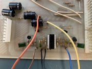
Hi all I have a PL 4000 Series II Preamp I am starting a restore on. Seems it has had the headphone jack wires removed and jumped back to the board. I have it figured out but the old copy of the Service Manual I have I just can't make out one wire color for W6. The headphone jack according to the schematic shows Left output going from W6 through the headphone jack and to W12. The left channel is W7 - headphone jack - W13. The bottom of the layout schematic page 12 PL40 Motherboard Layout is too blurry to find W6 wire color. I got all the other but call me a stickler I want the correct color of wire when I rebuild this. If anyone has a more legible page for that or can look in there's I would love to know that wire color.

thanks!
4000 SM page 12.png
 
Using your picture provided about, I see W17 - brown, W7 - blue, and W6 & W16 - black. Hope this helps.
 
I appreciate that. I see that now the arrow going to both W16 and W6. Interesting after looking at it with fresh eyes this morning I can see there is an error in the schematic. W6 does go to ground with W16 but the schematic shows it as Left Channel signal out before goes to the headphone jack. Furthermore my board (Series II) doesn't match the Series II Service manual in that area on the layout page. W 17, W6, W16, W7 aren't layed out like my board. W17 location is Right Channel out then there are 4 jumper points in a row all ground and then W7 to the right which is Right Channel signal out to the headphones. Easy to see when I ignore the error in layout page and compare the visual of the circuit with the schematic. W17 and W6 are mislabeled on the Layout page. Thanks to both you!IMG_4183.JPG
 
Last edited:
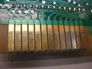
those funky daughter board connectors will give you shit-fits...... I can see the fur growing on them. That's the major issue with that unit.
 
I chucked one in the dumpster....... every time I turned it on, it did something different, well, it was the joystick version but ......
 
Yeah so it looks like an abundance of rosin on the original solder job put sticky all over the 10-20 mil pins which was never cleaned off. They all need cleaned after the recap. For connection issues on those pins if so inclined you can replace the female pins with trifericon female sockets which grab the pins on 3 sides instead of 1 and eliminate the problem. Years of ancient Wells Gardner arcade monitor repairs taught me that trick. I would abandon this thing but I'm getting board and its all have to fix up these days. I don't even know if it worked prior to my field strip, I never turned it on after acquiring it with the 400 S2 amp.
 
Last edited:
For anyone interested a fiberglass cleaning pop up brush like the ones used in pinball and arcade game repairs clean this pins well.
 
For anyone interested a fiberglass cleaning pop up brush like the ones used in pinball and arcade game repairs clean this pins well.

Can you explain more? I'm interested, but not familiar. Thanks.
 
sure let me see if I can post a link

https://www.eraser.com/products/fib...s/e111c-metal-body-coarse-fybrglass-eraser-2/

these are handy tools that use fibergalss strands on edge but only use them on edge never on their sides and only deploy them slightly. Also the debris from use is fiberglass powder nasty stuff for breathing and getting in your skin.

They have extra brush refills there too. You have to call them to order.
 
I think I paid $27 with a refill. There are $7 ones out there under a different brand
 
The “Rush FybRglass™ Eraser,” was originally designed for making typing and drafting corrections. In the 1940’s we found this eraser could be used to strip film insulation from magnet wires, and thus a product line was born.

Yeah, I strip a lot of magnet wire.................... NOT
 
Back
Top