Hi, I joined a couple years ago, with the expectation of picking up some Phase Linear gear. Took a lot longer than expected and appreciate any help you guys can offer with a 700 Series Two.
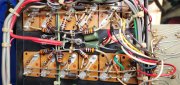
When I got it, the 700’s main fuse was intact, but the rail fuses were blown and wrapped with a double strand of 32ga copper wire. I try to make up for my lack of knowledge by being cautious, and decided to poke around before trying variac/dim bulb startup. I got the service manual and would like to share findings and photos here, along with some questions.
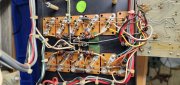
Left Channel 2 driver reads 11.2 rest read 9.4
Right Channel 1 and 2 all transistors read in the 2+ mega ohm range.
Thanks in advance for the help. I haven’t decided what to do with this amp yet, but regardless I like to fix things before making any mods.
When I got it, the 700’s main fuse was intact, but the rail fuses were blown and wrapped with a double strand of 32ga copper wire. I try to make up for my lack of knowledge by being cautious, and decided to poke around before trying variac/dim bulb startup. I got the service manual and would like to share findings and photos here, along with some questions.
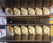
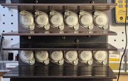
- The photos show new driver transistors in the right channel. I think all the rest is an original full complementary configuration?
- Readings with a Fluke 87 after cleaning each of the circuit contact points I used for the readings.
Left Channel 2 driver reads 11.2 rest read 9.4
Right Channel 1 and 2 all transistors read in the 2+ mega ohm range.
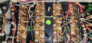
- I am stuck trying to figure out this high reading in the right channel. All right channel emitter resistors read .33 or close. The thermal relay and all grounding points to chassis all read about .3 ohms. Every collector plate reads .3 ohms to the collector rail. I pulled the caps in the right channel and they read correct. The only difference I could find on the right and left paired transistor boards themselves is that across the collector rails equals 10 ohms on the left and 1.2 megohms on the right. The 5W R1 resistor on the control board is bad, but if I jumper across it the readings on the transistors do not change. All diodes on the control board
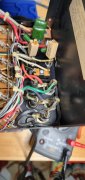
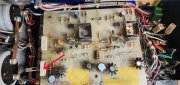
- The components shown on the main PCB layout Diagram 2.2 in the service manual are not present in this board.
Thanks in advance for the help. I haven’t decided what to do with this amp yet, but regardless I like to fix things before making any mods.