- Joined
- Feb 18, 2018
- Messages
- 191
- Location
- Southern Indiana
- Tagline
- ---6 and 7 days work week, no end in sight
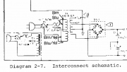
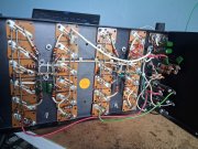
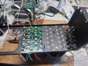
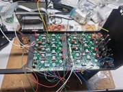
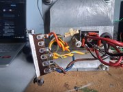
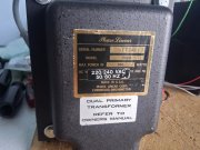
I bought this PL700 II 6 years ago on Ebay. This one was wired up for 220/240 volts. Transformer wires were solid brown on the bottom post, solid blue and yellow
w/brown stiped on the second post and yellow w/blue stripe on third post. I believe that solid brown and blue wires together on bottom post, nothing wired to second post and yellow w/brown stripe and yellow w/blue stipe wires together on third post. And the 12v solid orange and yellow wires on there own post. Also line fuse was 5 amp and not 10 amp. I'm going with White Oak chassis and that is the reason for transformer not attached to the original chassis.
Is this correct wiring for 120 volts?
Attachments
-
 3.5 MB Views: 7
 -
 3.5 MB Views: 7
 -
 4.2 MB Views: 6