Hi Mark
In an attempt to provide some additional insight.
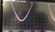
Many, but not all PL amps exhibit the purple heatsink phenomenon on the negative side, 2nd and 4th heat sink from the transformer. Parasitic oscillation is going on in the quasi construct leading to extra heat on these negative legs, leading to more heat in the heat sinks leading to purpling of these two stacks. The collector to ground (heat sink) capacitance in these legs is one of the contributing factor since the collectors are swinging with the audio signal on the negative half. This does not matter on the positive half because the collectors on this leg are tied to B+ and this extra collector to heat sink capacitance just contributes to extra B+ decoupling capacitance. This is a don't care situation as opposed to the quasi-comp negative half.
This high frequency oscillation also made the Zoebel work harder since these frequencies are typically above the turnover frequency of the Zoebel network. This is driving power from the negative output stage into the Zoebel as unnecessary dissipation.
Full comp fixes this condition as both positive and negative halves have the collectors at the B+ and B- potentials respectively. A superior arrangement. Also having each half as an emitter follower construct also contributes to better (lower) source impedance at the output.
Use a slow, low gain transistor (low gain-bandwidth) like the RCA410 in this critical quasi position to avoid this parasitic oscillation or better yet, convert your amp to full comp.
In an attempt to provide some additional insight.
Many, but not all PL amps exhibit the purple heatsink phenomenon on the negative side, 2nd and 4th heat sink from the transformer. Parasitic oscillation is going on in the quasi construct leading to extra heat on these negative legs, leading to more heat in the heat sinks leading to purpling of these two stacks. The collector to ground (heat sink) capacitance in these legs is one of the contributing factor since the collectors are swinging with the audio signal on the negative half. This does not matter on the positive half because the collectors on this leg are tied to B+ and this extra collector to heat sink capacitance just contributes to extra B+ decoupling capacitance. This is a don't care situation as opposed to the quasi-comp negative half.
This high frequency oscillation also made the Zoebel work harder since these frequencies are typically above the turnover frequency of the Zoebel network. This is driving power from the negative output stage into the Zoebel as unnecessary dissipation.
Full comp fixes this condition as both positive and negative halves have the collectors at the B+ and B- potentials respectively. A superior arrangement. Also having each half as an emitter follower construct also contributes to better (lower) source impedance at the output.
Use a slow, low gain transistor (low gain-bandwidth) like the RCA410 in this critical quasi position to avoid this parasitic oscillation or better yet, convert your amp to full comp.
Last edited: