GeorgeP
Journeyman
- Joined
- Mar 22, 2023
- Messages
- 129
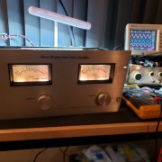
I all, I'm almost done with this 700 Watt on the bench:
1. Original Control board fully re-capped.
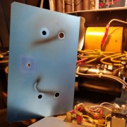
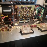
2. New 15,000 uF Power supply Caps, and 60 Amp Bridge Rectifier, Cut the GND plate to eliminate the original insulators on the + side of the caps, that arced over.
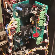
3. Installed Speaker relay protection boards, Watts Abundant 700W AND the 400W Relay boards set up using the UPC1237 Chip for lower offset detection.
I put the Relay "ON" green LED on the front panel, so I know the protection status.
4. Installed New Sealed 100K Volume potentiometers
5. Installed Custom added "STRIP LEDS" for the two meters, 3 strips each. Look good, modified the meter board.
6. Re-did the wiring harness, and GND Return lines.
Testing:
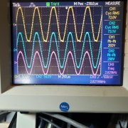
No load looks great at 200V Peak to Peak at the rails just clipping, both channels same.
Tested both channels into 4 Ohms at 40 Volts. Each channel the same, Very clean.
At greater than 400 Watts, the 5 Amp fuse blows, and relay board drops the load. GOOD!
New fuses and all still works fine, no issues.
Question. The amp will deliver more power, so...has anyone increased the 5 amp fuses to 6,7 or even 8 amps like was recommended on the 400Watt amplifiers for sinewave testing??? The 10 Amp Line fuse may have to increase a bit? This 700W has separate fuses to the +/-100V rails for each channel. I would like to see the Amp deliver 540 Watts into the 4 Ohms. Yes...I have a very High speed fan system, a pair 0f 6" high volume typed mounted on the heat sinks.
1. Original Control board fully re-capped.
2. New 15,000 uF Power supply Caps, and 60 Amp Bridge Rectifier, Cut the GND plate to eliminate the original insulators on the + side of the caps, that arced over.
3. Installed Speaker relay protection boards, Watts Abundant 700W AND the 400W Relay boards set up using the UPC1237 Chip for lower offset detection.
I put the Relay "ON" green LED on the front panel, so I know the protection status.
4. Installed New Sealed 100K Volume potentiometers
5. Installed Custom added "STRIP LEDS" for the two meters, 3 strips each. Look good, modified the meter board.
6. Re-did the wiring harness, and GND Return lines.
Testing:
No load looks great at 200V Peak to Peak at the rails just clipping, both channels same.
Tested both channels into 4 Ohms at 40 Volts. Each channel the same, Very clean.
At greater than 400 Watts, the 5 Amp fuse blows, and relay board drops the load. GOOD!
New fuses and all still works fine, no issues.
Question. The amp will deliver more power, so...has anyone increased the 5 amp fuses to 6,7 or even 8 amps like was recommended on the 400Watt amplifiers for sinewave testing??? The 10 Amp Line fuse may have to increase a bit? This 700W has separate fuses to the +/-100V rails for each channel. I would like to see the Amp deliver 540 Watts into the 4 Ohms. Yes...I have a very High speed fan system, a pair 0f 6" high volume typed mounted on the heat sinks.