Anyone understands how calibration is working?

Alex SE

Journeyman
Joined
Oct 10, 2021
Messages
283
Location
Sweden
Tagline
Amateur
#1
Thread title is probably not clear but I'll try to explain what I mean :)
Under the process of calibration, oscillator (or however it is called) is sending a two signals to a recording head. The one is for level adjustment (315 or 400Hz) and the other is for bias adjustment (8 or 10kHz probably). We all know that part so no rocket science.
There are some details I don't understand/know:
1. What is a level of those signals? -20db? 0db?
2. Can it be manipulated, for example, if it is -20, could it be adjusted to -18 instead? Does it affects calibration itself? I know it sounds weird but there is a reason why I need to do that.
3. If answer on a 2nd question is yes is there anybody who know how to do that (I'll attach here a pictures of oscillator scheme)
 

George S.

Veteran and General Yakker
Joined
Feb 18, 2020
Messages
5,033
#4
Depends on what unit your working on.
For example the Phase Linear deck has two oscillators, a 400 Hz and 10 kHz.
The oscillators frequency amplitudes are adjusted with trimmers.
400 Hz to -3.7 dBV (653mv).
10 kHz to -18.7 dBV (116mv).
The scan board needs to be put into test mode with shorting jumpers prior to adjustment.
Additionally, this is one of the very last adjustments, hence EVERY earlier adjustment must be correct and on level.
Adjusting the scan board input level comes next.
My Phase Linear deck project currently auto calibrates TDK D and SA, but has issues with MA.
Waiting on different caps for the record equalization section.
 

vince666

Chief Journeyman
Joined
May 15, 2013
Messages
1,078
Location
deep south of Italy
Tagline
I will not be missed! :p
#5
Thread title is probably not clear but I'll try to explain what I mean :)
Under the process of calibration, oscillator (or however it is called) is sending a two signals to a recording head. The one is for level adjustment (315 or 400Hz) and the other is for bias adjustment (8 or 10kHz probably). We all know that part so no rocket science.
There are some details I don't understand/know:
1. What is a level of those signals? -20db? 0db?
2. Can it be manipulated, for example, if it is -20, could it be adjusted to -18 instead? Does it affects calibration itself? I know it sounds weird but there is a reason why I need to do that.
3. If answer on a 2nd question is yes is there anybody who know how to do that (I'll attach here a pictures of oscillator scheme)
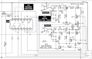
I suspect you are referring to the RS-B965, true?

That deck has, as you know, the inbuilt oscillators running at 400Hz and 8Khz.
There are two trimpots on the mainboard to adjust their levels (VR9 and VR10).
Of course, unless the PB level isn't quite a bit off, the test tones (once the rec gain is tuned to match tape's sensitivity) would go on tape at the proper level to evaluate the calibration.
Anyways, it's not that critical to check FR just at -20dB... a few dBs of difference don't really change the result.

Btw, there is a direct way to know at which level the test tones go to tape...
Do calibrate a tape as usual and then rewind and play the tape segment where you recorded the tones, to just see at which levels they are recorded on tape.

And, more in general, I never consider checking the frequency response alone (which is what you do by following the usual procedure) as the most proper method of calibrate bias but, hey, most decks out there were designed just with that only method in mind.
 

Alex SE

Journeyman
Joined
Oct 10, 2021
Messages
283
Location
Sweden
Tagline
Amateur
#6
I suspect you are referring to the RS-B965, true?
Do calibrate a tape as usual and then rewind and play the tape segment where you recorded the tones, to just see at which levels they are recorded on tape.
Yes, it is 965, since that all other RS-B's are in order. Unless it is 0db (which I doubt) it will be hard to determine since that peak meters are not precise at all at -20, but sure, it can give me a clue. It can't be -18 or -15. If so low, it have to be -20 than.

From beginning:
RS-B965, a great deck after mods is kind a weird. Which way?
1. PB level is obviously wrong adjusted from the factory. Yes it is!
SM says adjust output to 400mV (160 nWb/m test tape) which is equal to 545mV using 200 nWb/m ANSI, right?!
Well, when adjusted output is adjusted to 545mv a dolby level is about 225mv IARC which is less than 245mV where it actually should be. No problem, screw output, I've adjusted PB level at a Dolby IC as it is a better way. Now output is over 600mV but never mind, it's not important.
2. Peak meters are about 2-3db off.
200 nWb/m test tape should reach +2.8db (say +3) and I have about +5 or+6db.
No problem, there are resistors at the output (R41/R42, 10K) that can be replaced with a different values in order to lower the signal level. That affects both output and peak meters. There are even R555 and R556 on a display PCB, and those can be also replaced to adjust a peak meters.

Now problem:
Adjusting Peak meters to a proper level, which means +3db with 200 nWb/m tape affects even cal readings, that would say cal signal readings becomes about 2 peaks lower as it should. Turning trimpot VR10 all the way (bias cal) still don't pushing cal signal to a cal mark.

No, it's not disaster, I can simply adjust peak meters to a little higher readings and cal readings are gonna be fine, and, if no other way, I'll do so, but I'm really curious about how that calibration part is working and as a topic itself saying, can it be manipulated. One IC, about 20 resistors, 8 caps, 4 transistors, 2 trimpots... how the hell is that thing working??? It would be great if there was some kind of document that explains it but nope. Googling gives me only different topics about calibration itself.

1733601332352.png
I can measure a cal signal at IC9 pin 4 but that will not tell me anything since that it will be in mV, not in db.

1733602254987.png
 
Last edited:

vince666

Chief Journeyman
Joined
May 15, 2013
Messages
1,078
Location
deep south of Italy
Tagline
I will not be missed! :p
#7
Yes, it is 965, since that all other RS-B's are in order. Unless it is 0db (which I doubt) it will be hard to determine since that peak meters are not precise at all at -20, but sure, it can give me a clue. It can't be -18 or -15. If so low, it have to be -20 than.

From beginning:
RS-B965, a great deck after mods is kind a weird. Which way?
1. PB level is obviously wrong adjusted from the factory. Yes it is!
SM says adjust output to 400mV (160 nWb/m test tape) which is equal to 545mV using 200 nWb/m ANSI, right?!
Well, when adjusted output is adjusted to 545mv a dolby level is about 225mv IARC which is less than 245mV where it actually should be. No problem, screw output, I've adjusted PB level at a Dolby IC as it is a better way. Now output is over 600mV but never mind, it's not important.
2. Peak meters are about 2-3db off.
200 nWb/m test tape should reach +2.8db (say +3) and I have about +5 or+6db.
No problem, there are resistors at the output (R41/R42, 10K) that can be replaced with a different values in order to lower the signal level. That affects both output and peak meters. There are even R555 and R556 on a display PCB, and those can be also replaced to adjust a peak meters.

Now problem:
Adjusting Peak meters to a proper level, which means +3db with 200 nWb/m tape affects even cal readings, that would say cal signal readings becomes about 2 peaks lower as it should. Turning trimpot VR10 all the way (bias cal) still don't pushing cal signal to a cal mark.

No, it's not disaster, I can simply adjust peak meters to a little higher readings and cal readings are gonna be fine, and, if no other way, I'll do so, but I'm really curious about how that calibration part is working and as a topic itself saying, can it be manipulated. One IC, about 20 resistors, 8 caps, 4 transistors, 2 trimpots... how the hell is that thing working??? It would be great if there was some kind of document that explains it but nope. Googling gives me only different topics about calibration itself.

View attachment 84587
I can measure a cal signal at IC9 pin 4 but that will not tell me anything since that it will be in mV, not in db.

View attachment 84588
My friend...
I own two RS-B965, both modified by A.N.T., one "M" version (then like yours) and one "MF" version with Alps ferrite heads.

On both of these RS-B965, I didn't experience any of the metering issues you are describing... PB level on my decks is tuned properly (at the Dolby IC chips, of course) and when I measure the standard dolby level at the IC chip, the deck's meter show just the dolby segment on.
Of course, I didn't apply any modifies regarding the way the meters handle the levels, as you did and find it weird that you had to do that.

A big question, maybe also a bit of a stupid question, but it's a doubt I need to solve...
Are you reading the deck's meters properly?
As you just know, these meters have two ways of working, which you can switch from the "meter range" button.
Now, in the mode you get when you power on the deck (which is the broader and less precise one going from -30dB to +16dB and even more) , the actual segment refers to the level you can read on the number near the top right corner of the lit segment... and, in general, I just don't consider this metering mode as being that much precise.
And if you push the "meter range" button and switch to the other metering mode (the one which goes from -7db to +8dB where each segment is equal to one dB) the actual level of a given segment is the number you can see near the left corner of the lit segment... so, for example, the 0dB level is when the lit segment has the 0dB at its right corner and the actual segment is mostly over that small 0dB number.
So, each of these two meter modes have a different way to read the levels properly.
Of course, I always use this second metering mode, which is more precise and it's focused just on the interesting zone where you need to evaluate the peaks while recording a tape.

Most likely, what I described above is well known to you and then an unneded explaination... but, I preferred to write this anyway, who knows?
Also because, first times I used these decks, I got a bit confused in the way I must read the meters and, after all, this stuff might be useful for anyone else who might need to get this point clear.

Cheers,

Vince.
 
Top