oldphaser
Chief Journeyman
- Joined
- Sep 8, 2012
- Messages
- 850
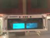
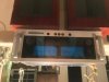
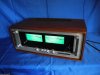
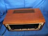
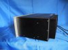
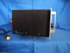
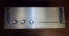
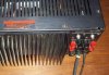
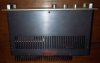
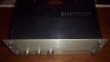
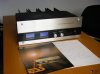
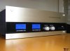
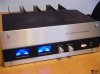
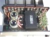
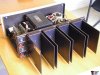
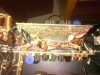
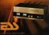
I ran into the following ebay ad copy which someone posted for an ESS Eclipse 500A they had for sale. If my memory serves me correct, Dean mentioned that Bob Carver was working on an amplifier for ESS (at Norm McFadden's house) after he left Phase Linear. I will double-check this with Dean when I get a chance.
http://www.ebay.ca/itm/ESS-Series-E...t-Excellent-Sounding-Super-Rare-/231810122495
The History of the ESS Amplifier Line:
The information on the internet regarding this amp is somewhat inaccurate and I’d like to clear it up:
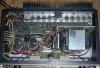
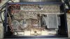
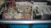
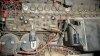
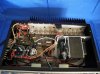
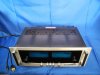
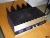
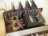
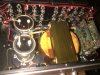
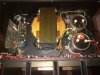
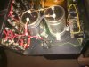
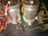
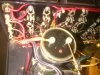
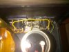
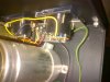
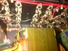
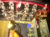
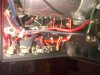
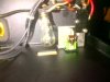
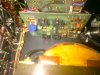
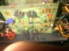
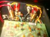
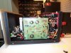
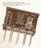
When I first bought the amp I read the posts that the amp was developed by the Late Bob Byrd. Nelson Pass told me that Bob Byrd was key and Pete Werbackalso worked in its development. I then emailed Bob Carver with some internal PICs of the amplifier…
Bob got back to me and said “That is my Circuit”! We need totalk and he told me this:
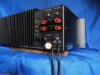
Back in the height of the Golden-Age Stereo days of the late 70’s,Dr. Oskar Heil was known to have the most advanced speaker systems with the Heil AMT 1. He needed an amplifier that would give what his superior speakers needed - lots of high-end power. Dr. Heil called his good friend Bob Carver and asked: “We need an amplifier to drive our Electrostatic speaker systems, would you be willing to help us? Bob agreed and traveled down to Sacramento and worked with ESS to design and build a prototype amplifier to properly drive the Heil tweeters/mids. This was after Bob sold Phase Linear to Pioneer and just as he was formulating plans for a new company which soon became Carver Corporation. In those days there were very few people who knew how to build high-end amplifiers. It was Bob Carver who was the driving force behind this project and Bob Byrd and Pete Werback continued the R& D once the amplifier circuitry proved itself in rigorous testing. In the early phase of development they were testing a prototype amp to drive a Heil driver to its maximum to see what it could handle. The driver caught on fire and they began work on a Speaker Protection circuit for this Amplifier. There were at least 3 generations of amplifiers before this Final Eclipse Series 500A. The Eclipse Series 500A was their last,best and most refined amp after many years of R & D and earlier amplifier production.
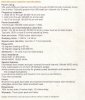
PROTECTION:
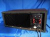
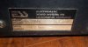
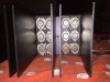
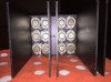
Active output transistor dissipation sensing circuit provides full performance into all load types either resistive or reactive, while maintaining absolute safety of the amplifier during direct short or extreme overload conditions. The amplifier is dual thermally controlled, to allow safe operation into extremely mismatched loads, and assure total de-energization in the event of continued operation into a short-circuit load.
Complete protection is provided to speakers and all internal components in the event of any D-C latch-up condition of the amplifier,including a forced state induced from outside sources. This is achieved via solid state circuitry without the requirement of output switching relays which often require early replacement.
http://www.ebay.ca/itm/ESS-Series-E...t-Excellent-Sounding-Super-Rare-/231810122495
The History of the ESS Amplifier Line:
The information on the internet regarding this amp is somewhat inaccurate and I’d like to clear it up:
When I first bought the amp I read the posts that the amp was developed by the Late Bob Byrd. Nelson Pass told me that Bob Byrd was key and Pete Werbackalso worked in its development. I then emailed Bob Carver with some internal PICs of the amplifier…
Bob got back to me and said “That is my Circuit”! We need totalk and he told me this:
Back in the height of the Golden-Age Stereo days of the late 70’s,Dr. Oskar Heil was known to have the most advanced speaker systems with the Heil AMT 1. He needed an amplifier that would give what his superior speakers needed - lots of high-end power. Dr. Heil called his good friend Bob Carver and asked: “We need an amplifier to drive our Electrostatic speaker systems, would you be willing to help us? Bob agreed and traveled down to Sacramento and worked with ESS to design and build a prototype amplifier to properly drive the Heil tweeters/mids. This was after Bob sold Phase Linear to Pioneer and just as he was formulating plans for a new company which soon became Carver Corporation. In those days there were very few people who knew how to build high-end amplifiers. It was Bob Carver who was the driving force behind this project and Bob Byrd and Pete Werback continued the R& D once the amplifier circuitry proved itself in rigorous testing. In the early phase of development they were testing a prototype amp to drive a Heil driver to its maximum to see what it could handle. The driver caught on fire and they began work on a Speaker Protection circuit for this Amplifier. There were at least 3 generations of amplifiers before this Final Eclipse Series 500A. The Eclipse Series 500A was their last,best and most refined amp after many years of R & D and earlier amplifier production.
PROTECTION:
Active output transistor dissipation sensing circuit provides full performance into all load types either resistive or reactive, while maintaining absolute safety of the amplifier during direct short or extreme overload conditions. The amplifier is dual thermally controlled, to allow safe operation into extremely mismatched loads, and assure total de-energization in the event of continued operation into a short-circuit load.
Complete protection is provided to speakers and all internal components in the event of any D-C latch-up condition of the amplifier,including a forced state induced from outside sources. This is achieved via solid state circuitry without the requirement of output switching relays which often require early replacement.
Last edited:

 Amazing pics