The " Save Time and Trouble With These Hints and Tricks" Thread!!

Gepetto

Administrator
Staff member
Joined
May 15, 2011
Messages
14,073
Location
Sterling, MA
Tagline
Old 'Arn Enthusiast
#1
I never found a solder sucker that worked as well as good solder wick does...but then again, I haven't looked at solder suckers in 10 years either.
Some rework hints:

If you intend to change the Backplane boards from one configuration to the other, make sure that the component leads you solder in are straight and NOT FLARED on the backside of the board. Flaring the leads will make it a bear to remove them. The Backplane boards have huge thermal mass on purpose because they need very large copper planes to carry the currents produced by this amp in driving the load. As a result of all that copper plane, it takes a good temperature controlled iron to make good solder joints for the connections into these planes. The boards are designed with no thermal reliefs around the vias on purpose in order to drive inductance and resistance of the amp connections to the minimum possible.

If you do not flare the leads, you should be able to rework your connections later on. It is also easier to sacrifice the component to be removed rather than salvage it. Cut the leads off at the body of the component leaving enough of a lead stub to grab it with a pair of tweezers. Apply heat carefully and once the solder is molten, grab the lead stub with the tweezers and extract it. It is always easier to remove a single lead, unattached to a component than to remove leads that are still attached to a component. Unless it is a very high value component, the board is ALWAYS more important than the component (this is close to rule #1). After you have the lead out of the hole, it will be much easier to clear the hole with a solder sucker or solder wick than with a component lead still in the hole.
 

Gepetto

Administrator
Staff member
Joined
May 15, 2011
Messages
14,073
Location
Sterling, MA
Tagline
Old 'Arn Enthusiast
#2
Whenever I replace a dual in line DIP package or similar, I take my pointy dykes and cut each lead at the body of the part, chuck the part and then extract each lead. Generally when you heat each lead it will stick to the tip of the iron due to surface tension of the solder so you do not even need to use tweezers. Then I just wipe the tip on the solder sponge to eject the scrap component lead and move onto the next lead. Quite a fast process.

Then I flip the board on its side in my Panavise so the plane of the board is vertical. I put the sucker on one side of the board and the iron on the other side, heat the solder and pull the trigger on the sucker.

It is very gentle on the board compared to trying to heat and suck from the same side of the board. Good for delicate boards.
 

laatsch55

Administrator,
Staff member
Joined
Jan 14, 2011
Messages
74,961
Location
Gillette, Wyo.
Tagline
Halfbiass...Electron Herder and Backass Woof
#3
Yep. Got a special little process or way of doing some electronic work that saves time, trouble and a whole lotta frustration?? This is where ya put em!!
 

premiumplus

Chief Journeyman
Joined
Feb 21, 2013
Messages
640
Location
Flint, MI
Tagline
Stuck in the 70's
#4
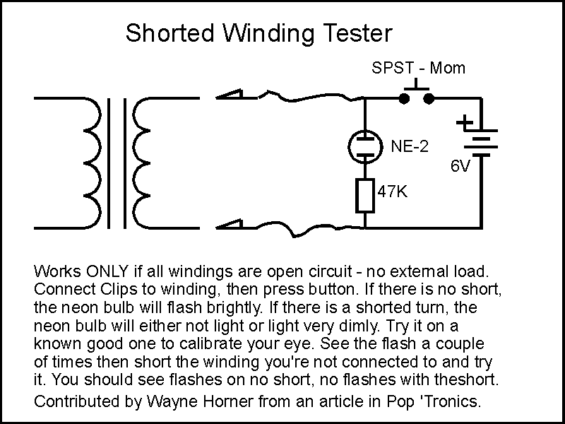
How to test for a shorted turn in any transformer


Here is a cool way to test a transformer if you suspect it has a shorted winding. This will detect even one shorted turn in your transformer...if you are trying to find an internal winding short your ohmmeter will never find it. This will. Here's a link to an article by R. G. Keen that explains the idea in more detail.
http://www.premierguitar.com/articles/print/the-super-secret-transformer-tester-1
Enjoy, Dave


laatsch55

Administrator,
Staff member
Joined
Jan 14, 2011
Messages
74,961
Location
Gillette, Wyo.
Tagline
Halfbiass...Electron Herder and Backass Woof
#5
Very, very cool Dave. I'll use that almost every day at work. We go through a lot of 480/120 control transformers.
 

Gepetto

Administrator
Staff member
Joined
May 15, 2011
Messages
14,073
Location
Sterling, MA
Tagline
Old 'Arn Enthusiast
#6
I KNEW that was messin with ya!!!! Me too. In order to get the solder all the way around it AND NOT see a bunch disappear to the other side was almost impossible.Now that you can apply some back pressure it will make it so much neater and more consistent on the miniscus.......VERY COOL FaboNav!!! Once again you have lived up to your nickname!!
I have a trick that I do to get a nice even meniscus, I spin the standoffs slowly with the shovel tip of my 80W iron once the solder gets molten. It spreads the solder nicely and makes a great joint.

PS: I get a lot of practice on the cap kits and the big standoffs. That is where I learned that trick.
 

Gepetto

Administrator
Staff member
Joined
May 15, 2011
Messages
14,073
Location
Sterling, MA
Tagline
Old 'Arn Enthusiast
#7
Joe, I've had some grip so tight it was easier to remove the tranny from the board, less collateral damage on a slip...
If you put a small screwdriver in the lower slit portion and give it a twist they come off easily. The lower section of the hat is separated by a horizontal cut which makes the lower portion that goes over the can quite flexible.
 

premiumplus

Chief Journeyman
Joined
Feb 21, 2013
Messages
640
Location
Flint, MI
Tagline
Stuck in the 70's
#8
Strain relief for bias transistor leads on the backplane

Hey guys,
Any thoughts on strain relief for the bias transistor leads? Every time I pull down a driver board to work on the backplane or probe the board I cringe, worrying about breaking a bias wire. Runaway output bias isn't a good thing! I wanted to wire tie them to the chassis ground lugs but the leads are a little short, then I thought about tying them to the emitter resistors but then there's the concern about the resistor heat.

What about putting a small lug on the bias transistor mounting screw to wire tie the leads to?
 

Gepetto

Administrator
Staff member
Joined
May 15, 2011
Messages
14,073
Location
Sterling, MA
Tagline
Old 'Arn Enthusiast
#9
Hey guys,
Any thoughts on strain relief for the bias transistor leads? Every time I pull down a driver board to work on the backplane or probe the board I cringe, worrying about breaking a bias wire. Runaway output bias isn't a good thing! I wanted to wire tie them to the chassis ground lugs but the leads are a little short, then I thought about tying them to the emitter resistors but then there's the concern about the resistor heat.

What about putting a small lug on the bias transistor mounting screw to wire tie the leads to?
I wire tie to the closest emitter resistor lead Dave. Nearly the first thing I do when I open up a 700. You can see it in this picture.

DSCN0012.jpg
 

laatsch55

Administrator,
Staff member
Joined
Jan 14, 2011
Messages
74,961
Location
Gillette, Wyo.
Tagline
Halfbiass...Electron Herder and Backass Woof
#11
DAVE!!!!!! You need FaboNav's DELXE MODEL 2's BIAS TRANNY BRACKETS!!!!! Yessireebob, they exist and they are bad ass!!!!Take a gander----AND TODAY ONLY ---your choice, black or white!!!! BuT WAIT!!! THERE"S MORE!!

IF YOu CALL IN THE NEXT 2 HOuRS, WE'LL INCLDE THAT PESKY LITTLE 4-40 NuT EMBEDDED IN THE BODY OF THE BRACKET --------AND----CALL WITHIN 20 MINTES AND GET YOR CHOICE OF LEFT OR RIGHT MODELS---OPERATORS ARE STANDING BY--=---
 

Attachments

Last edited:

laatsch55

Administrator,
Staff member
Joined
Jan 14, 2011
Messages
74,961
Location
Gillette, Wyo.
Tagline
Halfbiass...Electron Herder and Backass Woof
#15
Yep, special today only. Thanks for posting the application pic Dennis. That shows it beautifully.
 

Gepetto

Administrator
Staff member
Joined
May 15, 2011
Messages
14,073
Location
Sterling, MA
Tagline
Old 'Arn Enthusiast
#16
Yep, special today only. Thanks for posting the application pic Dennis. That shows it beautifully.
Dave they will be flipped around the other way in the 700 though. This is a PL400 picture. The device is close to the bottom in the 700 so they did a 180 on that amp.
 

NavLinear

Veteran and General Yakker
Joined
Apr 12, 2012
Messages
6,060
Location
SoCal
#17
Cap Zap

The cap zapper is shown in another thread but thought it would be good to include it here.

For those of us that don't like putting fingers close to big ass caps to discharge them here's something that I built allowing one to connect to the caps and to ground before shorting them together through a resistor. I used banana jacking hardware on the end of the leads so I can attach a multitude of clips. To use this I connect the leads with the toggle switch in the open position and then switch to either the 20 or 50 ohm 10 watt resistor to drain the energy. You can insert meter test leads in the 0.080" pin jacks to verify the voltage - just in case.
 

Attachments

premiumplus

Chief Journeyman
Joined
Feb 21, 2013
Messages
640
Location
Flint, MI
Tagline
Stuck in the 70's
#19
Yep, special today only. Thanks for posting the application pic Dennis. That shows it beautifully.
Well, I do believe I've gotta have me about 8 of those. 4 at least if quantities are short. I missed the 20 minute deadline, golldurn it...
Do you have a toll free number that I can call??? :happy7:
 

laatsch55

Administrator,
Staff member
Joined
Jan 14, 2011
Messages
74,961
Location
Gillette, Wyo.
Tagline
Halfbiass...Electron Herder and Backass Woof
#20
OK , in all honesty if you are going to install the pl700 backplane boards the FaboNav brackets are now a moot point. Not necessary as Q6 will then be mounted on the BC board, IF HOWEVER, you seek to capitalize on the COLLECTIBLE value, then they shall be on the way with the still not shipped 410's....
 
Top