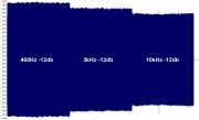
well... let's go a bit more in details in regards of the above matters... and will do examples referring to the Technics RS-B965 which is AlexSE's deck involved in this thread.
of course, being myself someone who never really studied electronics, my "knowledge" comes from what I could learn from other expert people (i.e. Alex/A.N.T. who i will never end to thank!) , by looking at schematics and by experimenting here at home on my decks while measuring the results... so, please, forgive me if i might say something the unproper way.
1) input loading resistors
They are those resistors which are placed just after the PB head and they are put in parallel, between the "+" of the PB head and the ground.
Input load resistance does influence the frequency response in the way that raising the resistance value raises the FR curve on the treble side but its influence on the FR is quite wide.
I usually see, on schematics, that heads with the lowest losses on treble (i.e. amorphous and ferrite) usually show lower input loading resistors at the PB amp while the heads with higher losses on treble (permalloy and even more sendust ones) have higher value resistors.
Values of such resistors usually range in the tens of thousands of ohms and can be as high as a couple hundreds of thousands of ohms or so.
2) input loading capacitors
Similarly as above, there are also small value capacitors (in the range of the hundreds of picofarads) put in parallel between the "+" of the PB head and the ground, usually just at the same place in the schematic as the above resistor.
Also here, raising the capacitor value will raise the response on treble but, this time, the range where the capacitance has its most evident effect is less wide and located just on the treble zone... also raising capacitor value will reduce the treble extension of the FR... so, i.e., if i raise the capacitor i might see a boost around 10Khz but then the response will start to fall a bit before at the extreme treble.
And, since the effect of the capacitor is less wide than what happens with the resistor, it might alter the FR in order to make it not regular (but it's also useful to fix a FR which was not regular, though).
3) PB EQ time constants
First off, the playback head itself acts like an inductor, then its own natural frequency response grows with frequency, then there are needed low pass filters to get, as a result, a flat playback frequency response.
So, we are talking about low pass filters of a given time constant which is related to the roll-off frequency.
We know the two standard PB EQ time constants are 70 and 120 microseconds (well, they are 3 because there is also the 3180us but we never touch it as it's usually OK as is on all decks).
120 is for type1 playback and 70 for type2 and type4 (unless we deliberately choose to record and play such tapes at 120).
And, to be more precise, the "120" setting is really a 120+3180 setting while the "70" setting is really a 70+3180 setting but, here, I will only focus on the 120 and 70 time constant while deliberately ignoring the 3180 one.
If you go and check the schematics on a few decks and calculate the actual time constants, you'll see they are almost never exactly 120 and 70 and, sometimes, they might also be quite far from the standard values.
Point is that the exact standard values work fine only on heads which show a FR close to the theorethycal optimum one, then the heads which are suppoused to work fine just at 120 and 70 are the ferrite and the amorphous ones.
Keeping (freely) quoting what Alex/A.N.T. shared over the years, if a ferrite or amorphous head is OK at 120 (focusing on the time constant for type1 mode, which i'll call "main time constant" , the other one will need to follow it proportionally) then a permalloy head will need a value between 130 and 140 , and a sendust head will need a value between 140 and 170.
Of course, to find out which is the best value, it's needed to test the PB FR with a proper calibration tape.
I usually see they set the time constants with resistors and capacitors... don't know if there are also other ways to do that but, here, i will refer to R and C because it's the only method I do know.
To calculate the actual time constant in microseconds, I do multiply the resistance in Kohm with the capacitance in nanofarads.
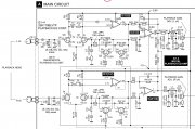
But let's go on directly with a practical example regarding the Technics RS-B965 cassette deck.

as you might see, this schematic shows a few useful hints... this deck does exist in more versions and, in particular, the PP version has amorphous heads while the other versions have permalloy heads.
Here in my description, I will refer only to the left channel then the same would be true on the right channel through the corresponding parts.
On this deck, we can see they did choose the input loading resistor R1 as 68Kohm for any versions of the deck.
And they did choose to add also the input "loading" capacitor C1 as 150pF on all the version except the PP version with amorphous heads.
but let's go at the PB EQ time constants...
On this deck, the PB EQ time constants are handled by R15 , R19 and C5.
The "120 microseconds" time constant, for type1 playback mode on all versions which aren't the PP one, is calculated this way:
( R15 + R19 ) * C5 = ( 15 K + 10 K ) * 5.6 nF = 25 K * 5.6 nF = 140 microseconds
while, for the PP version with amorphous heads, it becomes:
( R15 + R19 ) * C5 = ( 12 K + 10 K ) * 5.6 nF = 22 K * 5.6 nF = 123.2 microseconds
and the "70 microseconds" time constant, for type2 and type4 playback mode on all versions which aren't the PP one, is calculated this way:
R15 * C5 = 15 K * 5.6 nF = 84 microseconds
while, for the PP version with amorphous heads, it becomes:
R15 * C5 = 12 K * 5.6 nF = 67.2 microseconds
please, draw your own conclusions.
I hope it helps,
Vince.


