Ok thank you, I will go back and rebuild it Quasi comp. I appreciate the help.Ivan, you have a early 400 that was built with a quasi complementary point to point wired back wall, then the output transistors where selected and installed specifically for that quasi complementary back wall.
If you've not modified the back wall by rebuilding it full comp and installed the different output transistor configuration, then you need to build the control board quasi complementary to match it.
Also check your fuses for correct type and value. Some of these amps have had automotive fuses from the old Pontiac behind the barn or straight pieces of heavy copper wire.
Ask any question and we'll try to help. Nice job on the board!

You are using an out of date browser. It may not display this or other websites correctly.
You should upgrade or use an alternative browser.
You should upgrade or use an alternative browser.
Newly assemble pl14 rev G bias trimmers do not work correctly
- Thread starter CrazyIvan
- Start date
WOPL Sniffer
Veteran and General Yakker
Oh No, I'll go back and rebuild it.
Order some back plane boards and dump the old shit on the back wall, then build ALL of it FULL COMP.
I will rebuild the board quasi comp, Thank you for your help.Your output stage is quasi-comp....
WOPL Sniffer
Veteran and General Yakker
full comp is better. Don't go backwards
I will someday, funds are getting a little tight right now.Order some back plane boards and dump the old shit on the back wall, then build ALL of it FULL COMP.
WOPL Sniffer
Veteran and General Yakker
AND, if you are new, ask some questions. It saves issues like this.
- Joined
- Jan 14, 2011
- Messages
- 75,812
- Location
- Gillette, Wyo.
- Tagline
- Halfbiass...Electron Herder and Backass Woof
I will rebuild the board quasi comp, Thank you for your help.
You are very welcome Sir...
We're here to help bud...don't be bashful..
WOPL Sniffer
Veteran and General Yakker
I will someday, funds are getting a little tight right now.
$150 is cheap....................... Put your amp on hold, it's well worth it.
WOPL Sniffer
Veteran and General Yakker
I will someday, funds are getting a little tight right now.
Tearing it apart down the road is counterproductive.
MusicSteve
Journeyman
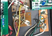
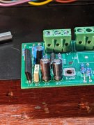
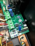
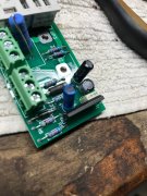
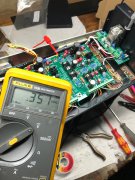
Hum,,,, I missed seeing the resistor. Its a Q-CompVotages are -/+ 82.3 DC on power capsView attachment 66507View attachment 66508View attachment 66509View attachment 66510View attachment 66511
Attachments
Last edited:
MusicSteve
Journeyman
Good Luck! Also make sure you change some diodes also,,,,,, you still need power to the RT board Pins 11 and 12I will try to get back to this tomorrow, thank you all for your help. I will keep you posted.
Skratch
Chief Journeyman
Looks like your amp has blown before, you have at least 3 different date codes on the output transistors. You may want to check and make sure none are open or shorted
MusicSteve
Journeyman
Did this PL 400 II work before the Upgrade?Hello, I recently added the DC protection, then new power caps from WO. I just assembled the pl14 rev G board. Started on a DBT no issues. went to adjust bias and my DMM readings are -.019 DC on both sides. Bias trimmers turned full CCW to start. Turning CW has no effect on the DMM. I am using board test points and white and red speaker outputs as test points. If I read between white and black or white and red I get .003 VDC. It doesn't seem normal to not get any bias adjustment. Any help is appreciated.
Last edited:
grapplesaw
Veteran and General Yakker
If you did power these caps installed backwards do not use them as that can possibly unwind the cap and open up all sorts of issues
yes it worked before the upgrade. it worked after the DC protection upgrade, it worked after the cap upgrade, the pl14 board was the next upgrade.Did this PL 400 II work before the Upgrade?
MusicSteve
Journeyman
That's a good way to do it , One step at a time , just fix the board and let us know what you changed , as a double check. Make sure you fixyes it worked before the upgrade. it worked after the DC protection upgrade, it worked after the cap upgrade, the pl14 board was the next upgrade.
the DOP board "Cap" like WOPL Sniffer pointed out and look at George pic. Also make sure you save all the Components you take out so if you do decide to got Full-c, you will have saved all the parts. Good luck
Last edited:
Quasi appears to be working now. redid board as required. Anyone know how decent Watts is to deal with? I bought the DCP board prebuilt. In trying to switch the cap, it took the trace out of the board when removing.
Attachments

Skratch
Chief Journeyman
He will make it right, he stands behind his boardsQuasi appears to be working now. redid board as required. Anyone know how decent Watts is to deal with? I bought the DCP board prebuilt. In trying to switch the cap, it took the trace out of the board when removing.