- Joined
- Jan 14, 2011
- Messages
- 75,824
- Location
- Gillette, Wyo.
- Tagline
- Halfbiass...Electron Herder and Backass Woof

Ed mentioned the article that suggests that analog scopes are better than digital scopes. Until I came across that article I thought I was the only person on the planet that felt that way. The R&D lab at my day job uses the popular Rigol DS1054 which is a really nice 4 channel, 50mhz, digital storage scope. It can be cracked to make it 100mhz. It only costs $350. I bought one and sent it back for a replacement because the trace was awful compared to the 30 year old Hitachi I use. The trace was so fat it left out details that are important such as oscillations riding on waveforms. The second Rigol scope was the same. I ended up keeping it because it's nice to have a digital storage function, but the Hitachi beats the pants off of it for quality of trace.
Well, this thread has made me get the book out and do more studying...that's a good thing..

Lee, If you are using a 10X probe, like it says on the display; that is a 30V P-P signal sine wave represented on the display at around 1KHz. UNLESS your scope compensates for the 10X probe to change the display to reflect the probe in use. Then it would be a 3V P-P sine wave. Digital scopes do weird things. Nice display, with notations right on the screen; but I like the old school analog display with the controls to change the display.It's one volt RMS, 2.88 peak to peak.....
Lee, If you are using a 10X probe, like it says on the display; that is a 30V P-P signal sine wave represented on the display at around 1KHz. UNLESS your scope compensates for the 10X probe to change the display to reflect the probe in use. Then it would be a 3V P-P sine wave. Digital scopes do weird things. Nice display, with notations right on the screen; but I like the old school analog display with the controls to change the display.
To me, VOMs or True RMS Voltmeters are for measuring DC or RMS AC. O'scopes are for measuring Peak-to-Peak AC. We need to see those peaks for noise or distortion, if any.
Yeh... That one looks good. Dual channel, too. Reasonable price.This is like the one I scored and they work perfectly fine for your everyday stuff. $160 and no need for service.
https://www.ebay.com/itm/Owon-PDS50...198870&hash=item3d8a214224:g:0XYAAOSwk25czrlY

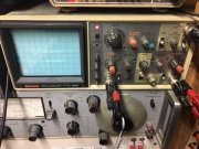
This is all a man needs (An OLD man that is)....
Vintage scope with vintage Phase Linear knob
View attachment 35328