
- Joined
- Jan 14, 2011
- Messages
- 75,894
- Location
- Gillette, Wyo.
- Tagline
- Halfbiass...Electron Herder and Backass Woof
After Johans conversion, I will attempt what I have been trying for 2 years, to finally get a WOPL over 600 watts a channel....it may even be closer to 700 into 8 ohms.
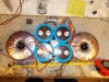
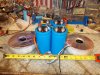
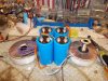
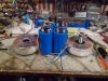
The heart of this is Joe's Driver boards and now that the 700 backplane boards are a reality we can finally try it. The ability to take a 700 chassis and cascade the entire output section and make it one complemenmtary channel is necessary to drive 4 ohm loads HARD , all day long. Each channel will have 2-800VA toroids paralled on the DC side with 4-35,000uf caps (like the one pictured). The idea behind the power supplies are to keep power supply droop to a minimum EVEN driving difficult loads. That, coupled with 22 output devices per channel will spread the current to acceptable levels. The heatsinks will be copper like the others I've done WITH DOUBLE THE EFFECTIVE RADIANT area. They will be 7' X 14"EACH, with 8 for each channel. Rail voltage will be +/- 118 volts DC. And that rail voltage being VERY STIFF. Each chassis will have it's own faceplate with one meter in the middle. there will be 4 separate enclosures --2-power supplies and 2 amp modules. The power supplies will weigh close to 60lbs each.
Each 1/2 of each power supply will have it's own soft start module limiting the inrush current to 3-1/2 amps , charge time of almost 4 seconds. Those soft start modules have also been designed by Sir Joe. The inside of the chassis will not have one iota of AC voltage(except the output) or AC current. Dc protect will be outboard(an idea also promulgated by Sir Joe. There will be no thermoswitch, cooling will be monitored with a temp sensor with a PWM controlled fan setup. DC rail fuses will be in the chassis where the transformer used to be, that is also where the power supply cable will enter, opposite of where the output will be.
This may seem extreme, but , it should drive any speaker system into the ground if necessary and make those really difficult loads sit up and pay attention...
If all my suppostions are less that what I believe they will be the power supplies are upgradeable to twice what they are now, I will add 2 more toroids , one on top of the original 2, and 4 more caps..
This will be a very time consuming project(not to mention the money) but I hope to have them ready for the RMAF....
I would like to publicly thank Sir Joe for his help and support for without that this project would not be possible, thanks Joe. Wish me luck folks.......I'm PUMPED!!!!!!!
PS. The original 700 power supply was a 1500va transformer, with 19,600uf capacitance, and 100+/- volts DC rails.......
PSS.... and if can be done in time the chassis will be made entirely out of copper also...
Attachments
Last edited:
")


