Troubleshooting

mlucitt

Veteran and General Yakker
Joined
Jun 24, 2011
Messages
3,373
Location
Jacksonville, FL
#1
Former military members will recognize this as "Professional Development" and I think it helps to share information and keep our skills sharp.
All are welcome to play along but this is directed to WOPL Builders, you know who you are...

Date: March, 13, 2021
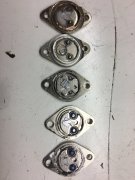
Scenario: WOPL 700B upgraded with WOA Rev G1 Control Board and Full Complementary WOA Backplane Boards with all new MJ21195/96 Output Transistors, also installed a Type Y2 300V AC-rated .01uF Safety Ceramic Capacitor across the Power Switch. Powers up perfectly under 100W DBT and Variac. Removed DBT and Variac and plugged directly into the 120VAC wall socket. Turned on the Power switch and immediately the 25A house circuit breaker opened. No input signal applied.

Initial Observations: Main Power Fuse was blown, removed power. Fuse replaced, power on and house circuit breaker tripped again and the Main Power Fuse was blown again.

Testing Theory: Looking for a short circuit.

Test Results (all tests referenced to chassis ground, Power Cord unplugged):
1) AC wire on Thermal Switch 1 to ground - no continuity.
2) AC wire on Thermal Switch 2 to ground - no continuity (redundant test).
3) Power Switch Terminal 1 to ground - no continuity.
4) Power Switch Terminal 2 to ground - no continuity
5) Power transformer primary 1 on Terminal Strip to ground - no continuity.
6) Power transformer primary 2 on Terminal Strip to ground - no continuity.
7) -100VDC B- screw (Black wires) on Bulk Cap to ground - no continuity.
8) +100VDC B+ screw (Red wires) on Bulk Cap to ground - short circuit.

Troubleshooting: Go!
 

mlucitt

Veteran and General Yakker
Joined
Jun 24, 2011
Messages
3,373
Location
Jacksonville, FL
#7
All good troubleshooting suggestions...
Rail fuses were good, Power Switch was good, Bulk Power Supply Caps were recently replaced.

George, the storage cap polarity had to be good because the amp came up fine on the DBT and Variac. A backwards cap may blow up, but certainly it would blow a rail fuse.

The problem turned out to be a blown 25A 200V Bridge Rectifier (Interestingly, Phase Linear used the same Bridge Rectifiers in both the PL400 and the PL700). The internal diode between the AC wire and the + Output was shorted. This short circuit provided a path from the B+ back through the transformer to the Center Tap ground wire/Star Ground. Never seen this happen before. I should have replaced it, I will replace all the original Bridge Rectifiers from now on.
Good thinking George.

Somebody else's turn to provide a troubleshooting challenge they solved.
 

wattsabundant

Chief Journeyman
Joined
Apr 26, 2011
Messages
848
Location
Central Ohio
#9
Going to a larger rectifier doesn't hurt, but it doesn't have any advantage either. The time/current curves of the 10 amp AGC line fuse indicates the fuse will go before the current through the rectifier can rise high enough to hurt it.
 

George S.

Veteran and General Yakker
Joined
Feb 18, 2020
Messages
4,590
#10
D'oh, of course, bad rectifier. The most common problem on the HP 174X series of scopes one of which I recently rebuilt. YouTube video shows a guy testing one of these rectifiers. It's working, he shakes it, it quits, shakes it, works again. How's that happen if it's "solid state"? Guess it's the tiny wires some devices have incorporated into them. If I get time and think about it, it would be interesting to open up a old PL rectifier and see exactly how it's constructed.
 
Last edited:

mlucitt

Veteran and General Yakker
Joined
Jun 24, 2011
Messages
3,373
Location
Jacksonville, FL
#11
I suggest using a
50 amp 1000volt rated Btidge Rectifier
KBPC5010T

mouser #905-KBPC5010T
Exactly the devices I have and I used one to replace the failed bridge rectifier. And when you buy (10), the unit cost is only $2.93. And, the manufacturer, GeneSiC Semiconductor, is in Dulles, Virginia, USA.
 

wattsabundant

Chief Journeyman
Joined
Apr 26, 2011
Messages
848
Location
Central Ohio
#12
I don't like the termination of the transformer to the rectifier. The solid conductor provides no strain relief. In Mark's case I doubt that a mechanical failure resulted in the rectifier failure. Unlike the TO3 outputs, I'm guessing that the rectifier is potted up and it's not possible to determine the root cause. For giggles, I attached a photo of some outputs with the covers ground off. I believe the top 2 are MJ15024's and the bottom 3 Mj21196's.
 

Attachments

George S.

Veteran and General Yakker
Joined
Feb 18, 2020
Messages
4,590
#14
Original rectifiers. Ground the one down until it's very thin. Those terminal lug bottoms have to be very close to the base. Wonder if they dropped a insulator sheet in first, then the components and compound. Failure could be a terminal shorted to base. When I get time I"ll dremel it out some. Not much in these, was expecting 4 conventional looking diodes.
 

Attachments

e30m3mon

Chief Journeyman
Joined
Feb 9, 2013
Messages
872
Location
Hudson Valley NY
Tagline
---
#15
Ya know...the rectifier occurred to me for a moment but then I figured nah. It worked fine during the DBT/variac bringup. Good sleuthing !

order will be placed for a replacement and installed during follow-up, along with the Belden coax.
What an awesome group you are!
 

mlucitt

Veteran and General Yakker
Joined
Jun 24, 2011
Messages
3,373
Location
Jacksonville, FL
#16
I did check all terminals to case with the Fluke multimeter and found zero continuity. Mine failed with a solid short between an AC and the +, I always thought that diodes would open and not short.
 

grapplesaw

Veteran and General Yakker
Joined
Aug 13, 2014
Messages
2,765
Location
Vancouver
Tagline
---
#17
I don't like the termination of the transformer to the rectifier. The solid conductor provides no strain relief. In Mark's case I doubt that a mechanical failure resulted in the rectifier failure. Unlike the TO3 outputs, I'm guessing that the rectifier is potted up and it's not possible to determine the root cause. For giggles, I attached a photo of some outputs with the covers ground off. I believe the top 2 are MJ15024's and the bottom 3 Mj21196's.
The middle one is very different with two parallel Circuits. What is it?
 

laatsch55

Administrator,
Staff member
Joined
Jan 14, 2011
Messages
74,244
Location
Gillette, Wyo.
Tagline
Halfbiass...Electron Herder and Backass Woof
#18
I've had one shorted rectifier and it had minus DC short to ac , I think. It wasnt blowing mains fuses...
 
Top