
SVC Bulletin #5199...Info Needed
- Thread starter Freecrowder
- Start date
You probably already have this, there are service bulletins addressing the relays at the end.https://www.vintageshifi.com/repert...ase-Linear-3000-Series-Two-Service-Manual.pdf. I just don't see that # anywhere.
Since the nitrogen and the inert gas have stable chemical properties, the nitrogen and the inert gas are not easy to react with other materials and are not easy to burn, the nitrogen and the inert gas are used as the protection gas of the relay to prevent burning, the service life of the relay is prolonged
The clamping diode works on the reverse EMF on the relay coil, has nothing to do with the contacts. The contacts arc less in the inert atmosphere and the goal is to have less arc. To me, this means the relay will last 150,000 cycles instead of 100,000 cycles at maximum voltage/current loads. I jest, but that is my opinion.
I agree about counter EMF, however a "clamping" diode isn't limited to just the relay's coil. Consider what the relay is switching.
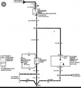
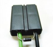
An example that comes to mind is an automotive AC clutch coil. You may find a 1N4001 diode in the plug itself reversed biased.
Older GMC / Chevys had this setup for years.
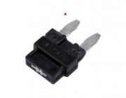
Newer versions have a "fuse looking" diode in the fuse box for this function of protecting the relay contacts....
If the diode was missing you would weld relay contacts all the time !
M
An example that comes to mind is an automotive AC clutch coil. You may find a 1N4001 diode in the plug itself reversed biased.
Older GMC / Chevys had this setup for years.
Newer versions have a "fuse looking" diode in the fuse box for this function of protecting the relay contacts....
If the diode was missing you would weld relay contacts all the time !
M
Attachments
-
 45.1 KB Views: 8
 -
 8 KB Views: 7
 -
 23.8 KB Views: 5
Well, we are not switching an automotive AC clutch coil. You are talking about large inductive loads across the relay switch contacts. I am not aware of any inductive loads inside the Phase Linear 3000 Series II preamplifier relay circuits.
When a relay is used to control an inductive device (relay coil, solenoid, transformer, small motor, etc.), the energy stored in the inductance in the device will subject the relay contacts to a high voltage when the relay contacts open. When the contacts open, the contact gap is initially small. Arcing across this contact gap can occur immediately after the contacts open. This can happen in resistive as well as inductive loads, but inductive loads generate a higher voltage and this causes increased arcing. Increased arcing decreases contact life. Direct current (DC) inductive circuits typically use a diode to prevent the high voltage. The diode in the circuit is called a suppression diode, flyback diode, freewheeling diode, or catch diode. However, a diode cannot be used in an alternating current (AC) or audio circuit. AC arc suppression requires the use of a metal-oxide varistor (MOV), a bidirectional transient voltage suppressor (TVS) diode, or an RC suppression network. An RC suppression network is also called a snubber. The various arc suppression methods have various advantages and disadvantages. Using no suppression is also an option if life is adequate without it.
(most of this was from a Littlefuse application note)
- Joined
- Dec 7, 2020
- Messages
- 12
Another important point of the Flyback diode is that it is connected in reverse bias in relation to normal current flow operation of the inductive load(DC). Therefore it is essentially out of the circuit under normal current flow. When an inductive load is turned off and the collapsing field generates it's voltage it is in the opposite polarity as the applied voltage. Then the back EMF sees the diode shunt and is essentially shorted out.
Mohawk, you have provided an Air Conditioning circuit schematic drawing showing a diode connected across a coil. Then you say it's "protecting relay contacts" because the diode is connected across the load. It is not. This is not even a relay, it's a magnetic coil attracting the metal plate connected to the AC compressor pulley.
The Air Conditioning relay is in the dashed box above your arrows and there is NO diode across that relay coil nor the relay contacts.
Trust me on this. I am a certified Air Conditioning and Refrigeration (AC&R) mechanic and a very experienced electronics technician doing this silly stuff for 50 years (since age 14).
Mlucitt,
Just a couple of points to make ...
My original point was a diode can be used to "protect" relay contacts...
As seen in the diagram, the diode is indeed across the coil, that is the load, (the clutch coil itself)
I don't remember saying the diode is across the contacts, if I I did I stand corrected ... just saying that we can use a diode to protect relay contacts from arching
The relay is indeed in the dashed box, the relay controls or actuates the cultch coil.
Once the relay is disengaged, the clutch coil's magnetic field collapses and we get a decent counter EMF (AC) that is now negated getting back to arch at the relay contacts by the diode being across that load in reverse bias...
I am also certified 310S & 310T auto / truck mechanic ... 30 ish years..... Cheers !
M
- Joined
- Dec 7, 2020
- Messages
- 12
The diode "protects the contacts" of the relay that is in series with the inductive load turning it off and on. It does not protect the contacts that are associated with that inductive load if it happens to be a relay. In that case many times they use a snubber circuit under the trademark "QeunchArc" across the associated contacts(AC). QuenchArc= RC network.
- Joined
- Dec 7, 2020
- Messages
- 12
OK so back to the original issue. From what I read the relays are no longer made and hard to source?? No adapter boards out there anywhere used with current type relay?? Reading the SM on that preamp it talks about a relay regulator circuit upgrade but I do not find that anywhere. Any info out there? When I press the high level input (green LED) it doesn't always defeat the other high level that is already on. So two greens on at same time. Haven't cleaned any input switches yet but planning on it.