Smokey Bears Akai GX-635D

30Weight

Journeyman
Joined
Jun 17, 2014
Messages
62
Location
Spokanistan,Waaahh
Tagline
---
#1
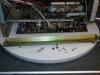
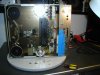
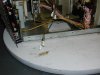
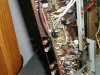
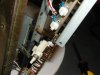
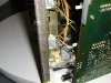
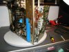
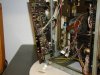
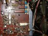
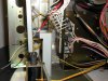
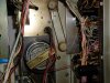
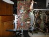
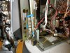
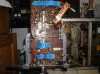
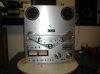
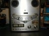
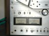
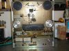
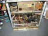
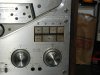
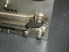
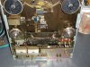
Split the cases on the smoke damaged Akai to take a closer look at it. This one will be more challenging I believe. Extensive smoke & water damage. Someone used abrasive cleaner on the FP,removed a lot of the labeling. Thankfully they noticed the damage before doing the entire front. Also missing an inner,metal side panel. The sheet metal screws rammed into threaded machine screw sockets have me cringing. The seals on some of the head alignment screws are broken also.......oh no,here we go. I think I'm going to earn this one. The amp board's also chock full of the original 458 transistors. Gonna try and save it 1st,salvage it if that's a no-go.This one's gonna keep me off the streets for a bit......

P1010110.jpg P1010112.jpg P1010121.jpg P1010124.jpg P1010111.jpg P1010114.jpg P1010122.jpg

Nick,when removing the outer level ring go easy on prying the keepers out. Old,brittle plastic.....difficult and usually expensive to replace.....but you've got spares :)

P1010125.jpg
 

30Weight

Journeyman
Joined
Jun 17, 2014
Messages
62
Location
Spokanistan,Waaahh
Tagline
---
#3
Got started removing the amp board. Nick,if there's anything you've got a question on or want pics of while it's apart,let me know. Removed the two lower side panels. Lay it on its side,gets a little unstable after that. On the BP gently pry the 2 plastic rivets anchoring the RCA jack plate,remove the screws,3 more accessed from inside anchoring the board. The panel drops off. Remove the shaft nuts from the FP controls and the screws,don't forget the 2 holding the led board on.They're accessed from inside. Taped the vu meters for support. Labeled and pulled the removable connectors from the amp board. The amp board is ready to slide free,from the back,of the chassis. Travel is limited tho. There are a couple of mechanical switch linkages that will fall free at this point. Good idea to draw or photo their orientation,might be awhile before it's reassembled. Several things need unsoldered now. The vu meter feeds,I usually unsolder from the board. Detaching at the meters might be easier,but less forgiving of error. There are a couple leads on the switches that need removed also. The one photo shows the wire wrap terminal strip that needs unsoldered from the board. Good idea to mark its orientation prior to removal,hate to reverse it. The amp board will be free of the chassis now. Ready to put in the vice and get serious. Good time now to order a new counter belt and de-ox the controls.

P1010091.jpg P1010092.jpg P1010093.jpg P1010094.jpg P1010095.jpg P1010097.jpg P1010098.jpg P1010099.jpg
 

Nick Danger

Veteran and General Yakker
Joined
Apr 28, 2013
Messages
2,777
#4
Thanks for the info and pics, 30W! Always nice to have a little info before I go rummaging around inside of an unfamiliar deck.
 

30Weight

Journeyman
Joined
Jun 17, 2014
Messages
62
Location
Spokanistan,Waaahh
Tagline
---
#5
Hey Nick,it's no trouble at all. I like to have a map and compass handy when I explore the wilderness too. Here's a couple more pics of what you're in for. I steered you wrong on one. It's a lot easier to just clip the leads on the wires running to the long switch (ID them 1st of course) than it is to unsolder them. Clean things up when you have it separated from the chassis. The vu meter leads are kinda tight,they left some slack in the other wire runs tho. Be careful unsoldering the wire wrap strip from the pcb. The previous one came off as one unit,for some reason this one wanted to come apart as individual leads. Could have gotten ugly. Included a pic of the mechanical linkage and how it fits properly (for re-assembly). The 2 holes ( blue arrows) in the plastic slides fit into the 2 arms that drop from the solenoid actuated crossbar still attached to the chassis (also blue arrows),for reassembly. It gets frustrating if you overlook this fitment.....I can tell you all about that. Also included a pic of the counter belt.

P1010101.jpg P1010102.jpg P1010103.jpg P1010104.jpg P1010105.jpg
 

30Weight

Journeyman
Joined
Jun 17, 2014
Messages
62
Location
Spokanistan,Waaahh
Tagline
---
#7
Me too,couldn't do the job without it. I use a thrift shop picture frame (of stout construction) to expand the base footprint. Adds a bit more stability. The suction base of the panavise sticks to the glass in the frame well.
 

30Weight

Journeyman
Joined
Jun 17, 2014
Messages
62
Location
Spokanistan,Waaahh
Tagline
---
#8
It's transistor time! The main troublemakers are TR1-2-3-4-7-8-9,2 of each. 1 per channel. Check the entire board thoroughly. This one threw me a curve ball. TR5-6-10 were also 458s,2 of each. 1 per channel. The previous 635 I did had other transistors there. I used Fairchild KSC1845FTA's for the swap. Mouser # 512-KSC1845FTA,.15 each. The transistors face different directions on the board,do them 1 at a time to avoid confusion in case of interruptions. The leg configuration of the 1845 (E-C-B) is the same as for the 458. In case you do get confused the B leg position is marked on the pcb. Flow some fresh solder on the old joints prior to removing the old solder. Flows easier and more cleanly. Included a pic of some test tools that come in handy for this. Bought them at MCM awhile back,worth the money. There might be other issues with the board but this is a well known problem. Yes,8 of the 20 458s failed outright. 4 of the rest were leaky. Also included a shot of the old/new transistors for comparison. You can see the "root rot" on the 458s. Now to clean the board and controls,replace the counter belt and reassemble.

P1010115.jpg P1010117.jpg P1010118.jpg P1010119.jpg
 

laatsch55

Administrator,
Staff member
Joined
Jan 14, 2011
Messages
74,244
Location
Gillette, Wyo.
Tagline
Halfbiass...Electron Herder and Backass Woof
#11
The used portion on the left side came from a project of bending 1/8" brass to the correct radius for RCA jumpers.....
 

30Weight

Journeyman
Joined
Jun 17, 2014
Messages
62
Location
Spokanistan,Waaahh
Tagline
---
#12
Gotta love homemade tools.They're always application specific,cheap and more functional than many you'd spend money on. The ol' gal cleaned up good. It has some other issues. Unkind hands had been deep inside this one before. Looks like it might have gotten dropped,no surprise considering it's past. Both spindles wobble.Have to check table height. R channel works great. L channel appears dead,no audio heard,vu meter asleep. Funny thing tho,if I run the headphone plug slowly thru the jack I can find a sweet spot (not fully seated) where I hear both channels,vu meter still sleepy. 1 of the reel blocks,with the tensioner arm,is all jacked up. Doesn't move freely. The RH reel motor was kinda working,speed was way off. Had to adjust that with too much pitch control. All that circuitry/hardware is at the top of the deck. That area sustained most of the damage from the smoke and water. The more I fixed it the less it worked. That's about as far as I wanted to go today,time to switch the tools to off. Let the subconscious wrestle with it and start fresh later.

P1010118.jpg
 

30Weight

Journeyman
Joined
Jun 17, 2014
Messages
62
Location
Spokanistan,Waaahh
Tagline
---
#15
Making progress in baby steps here. I thought the RH reel motor had failed. It would slow and stop,attempt to restart and stop. Would not drive a load at all,even a 7" takeup reel. Runnin' hot too,saw up to 140degF on it. The motor output shaft was sticking in its bearings. Probably corrosion caused. Soaked it in some light oil,it's a sealed unit,let it flow down the motor shaft. Sprayed some contact cleaner on the corroded windings too. Hand spun it until it felt smooth. Ran it installed,no load. Put the table and brake assembly,with a 10.5" reel on and tried it under load. Temperature stable at 115degF. Everything functioned OK,both directions. Whew!

The jacked up reel block was caused by one of the external front panel trim pieces. Jammed in there tight. That must have been an interesting story. Works fine once that was removed.

The left channel issue was self inflicted. I put the very last transistor in backwards........brain fade! Yeah,I can't even read my own directions...........

P1010121.jpg P1010122.jpg
 

Nick Danger

Veteran and General Yakker
Joined
Apr 28, 2013
Messages
2,777
#17
Way to go, 30W! Glad to hear that you are getting close to having this deck up and running again.
 

30Weight

Journeyman
Joined
Jun 17, 2014
Messages
62
Location
Spokanistan,Waaahh
Tagline
---
#18
Thanks Nick. Hope this thread makes your task easier. Going to check the record function,both directions,next. Another one saved from parts status. Don't know what I'll do with it.....outa room here at the shack. Friend of mine keeps asking me for an R2R deck at his shop to sell. Gets a lot of requests for them. This being Spokane everyone wants them cheap too. No money in it yet. Probably sell it thru him at a reasonable price,lower than market average. Let someone else get into the hobby with it. For a $50 outlay for it I have some wiggle room on the price :)
 
Top