Time to play “Stump the Experts”. I am working on a 700b I’ve had for a few years. I’ve installed one of Joes rev g boards along with new power supply caps, rectifier, arc fuse holders, input jacks, iec outlet, dc protect board, new wiring, and new resistors on the original backplanes. Now for the problem. I installed the first three rows of transistors separately, monitoring bias voltage. The board has 15.4 volts +&-. Everything looked great. I was using a variac and DBT which was glowing a very dull orange color. I installed the 4th row and that is when disaster struck! One of the screws for the transistor closest to the transformer made contact with the 10 ohm resistor that sits there. When I increased the voltage going slowly the bulb stayed bright and I lost the bias reading from the test point. I don’t think I went beyond 30 volts on the variac. No smoke, no pops, no flames. I removed that 4th row and powered it up again and the bulb was orange like it should be. Still have 15 volts on the board. At this point I’m guessing I toasted one or more transistors on the board but this is where my skills are lacking. I’m not sure which components might have been affected. I’ll also need help testing them. I’ve been a member here for a number of years but this is my first adventure in working on one of these. I’m a retired mechanic by trade and have a bad habit of trying to resurrect anything broken. I have a variac, DBT, and a Fluke meter, and a large supply of hammers if necessary. Any and all help, comments, criticism, or anything else would be greatly appreciated. Another question; why does this affect bias on both channels?

Self inflicted wound
- Thread starter Steve K
- Start date
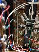
Steve can you post a pic of the screw location where it hit the resistor? That screw is bringing in +100VDC to one side of that bias resistor or the other (either the amp output or the bases of all the topside transistors) . Either way it would be good to know which it hit.
Can you describe more of what you mean by "and I lost the bias reading from the test point. "
Can you describe more of what you mean by "and I lost the bias reading from the test point. "
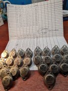
Download and print out the data sheets for the suspect transistors. Number each transistor with a sharpie. On a clean sheet of paper, make a spreadsheet for testing results. The photo shows the results from my testing original 700 Pro transistors with a cheap old Radio Shack Micronta transistor tester. You can do the same with a digital multimeter set to diode function.
I think the 700 S2 manual gives instructions for testing outputs in circuit.
I think the 700 S2 manual gives instructions for testing outputs in circuit.
Attachments
-
 4 MB Views: 10
- Joined
- Jan 14, 2011
- Messages
- 74,244
- Location
- Gillette, Wyo.
- Tagline
- Halfbiass...Electron Herder and Backass Woof
- Joined
- Jan 14, 2011
- Messages
- 74,244
- Location
- Gillette, Wyo.
- Tagline
- Halfbiass...Electron Herder and Backass Woof
- Joined
- Jan 14, 2011
- Messages
- 74,244
- Location
- Gillette, Wyo.
- Tagline
- Halfbiass...Electron Herder and Backass Woof
That connection caused by the screw effectively put B+ voltage on the output rail. Based on what you said about the variac being at about 30VAC, the B+ would have been in the range of +25VDC. To the extent that it could with the DBT in place, the lower half of the amp would be fighting like hell to bring that voltage back down to zero. The outputs and drivers would have all have their B-E junctions reversed biased beyond the absolute maximum spec of negative 5V but if it did any damage, hard to say.
With Row 4 now out, are symptoms back to normal again or is the DBT glowing brightly? Are you sure something is damaged or are you just jumping to that conclusion?
With Row 4 now out, are symptoms back to normal again or is the DBT glowing brightly? Are you sure something is damaged or are you just jumping to that conclusion?