Resistor behavior

62vauxhall

Veteran and General Yakker
Joined
May 14, 2014
Messages
2,287
Location
Southwest Kootenays BC
Tagline
No such things as bad days, just bad moments
#1
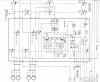
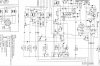
This is not PL related but I've been trying to figure out why a 1 watt, 56 ohm wire wound resistor is heating up. It would be too hot to touch if I kept power applied.

I pulled it from the circuit and it does measure about 56 ohms. There is the correct 24V going in to one end and around 13 volts at the other but it's supposed to be 20.5.

As I bring the variac up, the resistor heats up fairly quickly once it starts receiving 24 volts. Since it's dropping more voltage than it should, it seems logical that would account for the high temperature.

But I don't get why the resistance checks out. That being so, it cannot be defective, can it?

Any thoughts?
 

laatsch55

Administrator,
Staff member
Joined
Jan 14, 2011
Messages
74,216
Location
Gillette, Wyo.
Tagline
Halfbiass...Electron Herder and Backass Woof
#2
Your problem is current related, not resistance related. Something on one side is drawing too much current...
 

62vauxhall

Veteran and General Yakker
Joined
May 14, 2014
Messages
2,287
Location
Southwest Kootenays BC
Tagline
No such things as bad days, just bad moments
#3
Dang. And the schematic only has those two voltages figures printed on it. 24 volts going into the resistor and 20.5 on the other side - which I physically measured at 13 volts.

So high current draw does not sound like a short or is that an incorrect assumption?

If so, then I guess it's not a bad trace or solder connection but a faulty component of some kind? Maybe a variable resistor?
 
Last edited:

Gepetto

Administrator
Staff member
Joined
May 15, 2011
Messages
13,536
Location
Sterling, MA
Tagline
Old 'Arn Enthusiast
#4
Dang. And the schematic only has those two voltages figures printed on it. 24 volts going into the resistor and 20.5 on the other side - which I physically measured at 13 volts.

So high current draw does not sound like a short or is that an incorrect assumption?

If so, then I guess it's not a bad trace or solder connection but a faulty component of some kind? Maybe a variable resistor?
You should share the schematic so we can offer some suggestions
 

62vauxhall

Veteran and General Yakker
Joined
May 14, 2014
Messages
2,287
Location
Southwest Kootenays BC
Tagline
No such things as bad days, just bad moments
#5
I'd love to do that but all I can access are PDF's of the service manual and if it's possible to isolate the page(s) containing the relevant schematic(s), I do not know how to do that.

The only thing I seem to be able to do is copy and save the entire manual as a PDF document and I doubt a "print screen" would be much if any good.
 

Gepetto

Administrator
Staff member
Joined
May 15, 2011
Messages
13,536
Location
Sterling, MA
Tagline
Old 'Arn Enthusiast
#6
I'd love to do that but all I can access are PDF's of the service manual and if it's possible to isolate the page(s) containing the relevant schematic(s), I do not know how to do that.

The only thing I seem to be able to do is copy and save the entire manual as a PDF document and I doubt a "print screen" would be much if any good.
use the Windows snipping tool
 

62vauxhall

Veteran and General Yakker
Joined
May 14, 2014
Messages
2,287
Location
Southwest Kootenays BC
Tagline
No such things as bad days, just bad moments
#7
OK. Seems I have next to zero understanding of Windows. I had no idea that feature existed so had to Google it to see how to use it. I saved the images as jpeg's thinking that was as good as any.

There is only one board I'm dealing with, from a Teac A2300SD R2R. The manual refers to it as the Bias Oscillator but I believe it also contains the power supply or what was I was told - AC Regulator.

The overheating resistor is R27 which is fed from pad 37 and hopefully this makes sense.

The entire board is disconnected with the exception of a black (presumably) ground going to hole 9 and 2 blue wires going to holes 26 & 27. This arrangement does produce 24V (closer to 25V) at pad 37 which is correct. However, when I re-connect a wire from pad 37 to hole 4 thereby feeding 24V to R27, it heats up.

There is a voltage figure of 20.5 volts on the opposite side of VR1 which to my understanding, should be coming directly from R27 and be no less than that. Yet, what I read coming out of R27 is about 13 volts.

Teac A2300SD bias oscillator.jpg Teac A2300SD power suppy.jpg

EDIT: FWIW, There are only 4 transistors on this board which I removed and checked and they are OK as are their emitter resistors. Since it was suggested to me that capacitors C14, C15 & C22 might be suspect and I had equivalents on hand, I replaced them.

Must get to sleep now. Spent 17 hours on duty and I've got to get up in 5 hours.
 
Last edited:

Gepetto

Administrator
Staff member
Joined
May 15, 2011
Messages
13,536
Location
Sterling, MA
Tagline
Old 'Arn Enthusiast
#8
OK. Seems I have next to zero understanding of Windows. I had no idea that feature existed so had to Google it to see how to use it. I saved the images as jpeg's thinking that was as good as any.

There is only one board I'm dealing with, from a Teac A2300SD R2R. The manual refers to it as the Bias Oscillator but I believe it also contains the power supply or what was I was told - AC Regulator.

The overheating resistor is R27 which is fed from pad 37 and hopefully this makes sense.

The entire board is disconnected with the exception of a black (presumably) ground going to hole 9 and 2 blue wires going to holes 26 & 27. This arrangement does produce 24V (closer to 25V) at pad 37 which is correct. However, when I re-connect a wire from pad 37 to hole 4 thereby feeding 24V to R27, it heats up.

There is a voltage figure of 20.5 volts on the opposite side of VR1 which to my understanding, should be coming directly from R27 and be no less than that. Yet, what I read coming out of R27 is about 13 volts.

View attachment 30223 View attachment 30224

EDIT: FWIW, There are only 4 transistors on this board which I removed and checked and they are OK as are their emitter resistors. Since it was suggested to me that capacitors C14, C15 & C22 might be suspect and I had equivalents on hand, I replaced them.

Must get to sleep now. Spent 17 hours on duty and I've got to get up in 5 hours.
Is the bias oscillator formed by Q20 and Q21 running? If it is stalled, you will have potentially high current running through your 56 ohm resistor causing it to heat up. It is meant to be running all the time and dumps either into the record head or into the dummy inductor depending on the position of the record relay.
 
Last edited:

62vauxhall

Veteran and General Yakker
Joined
May 14, 2014
Messages
2,287
Location
Southwest Kootenays BC
Tagline
No such things as bad days, just bad moments
#9
Negative - not running. Nothing currently connected to that board at all except wires from the transformer.

Would connecting only the shielded leads constitute running - or should I go ahead and connect everything?

I was considering doing the latter anyway but with the exception of the shielded leads. They are still attached to original board and I did not want to apply heat to them unnecessarily until (totally optimistic thinking) the replacement board could be re-installed. But by the sounds of things, that would have been a waste of time.


As an aside: Hypothetically, if the center conductor of one of those leads was disconnected from the original board (as it currently is and may have been for quite some time) could that have been responsible for resistors (more than one) burning up on the original board?
 

rtp_burnsville

Chief Journeyman
Joined
May 1, 2011
Messages
899
Location
Savage, MN
#10
If the switch is in the position shown on the schematic I would check the capacitor C22 and C29. It looks to me as if those caps go to ground. If one or both are shorted the current would be higher as Lee had mentioned. I assumed that the +24V is from the power supply rail and that the small cap is also not shorted (very unlikely that it would be).

Robert
 

Gepetto

Administrator
Staff member
Joined
May 15, 2011
Messages
13,536
Location
Sterling, MA
Tagline
Old 'Arn Enthusiast
#11
If the switch is in the position shown on the schematic I would check the capacitor C22 and C29. It looks to me as if those caps go to ground. If one or both are shorted the current would be higher as Lee had mentioned. I assumed that the +24V is from the power supply rail and that the small cap is also not shorted (very unlikely that it would be).

Robert
If the bias oscillator is not running, it presents a ~16 ohm short to ground. It needs to be understood why the bias oscillator is not oscillating.
 

62vauxhall

Veteran and General Yakker
Joined
May 14, 2014
Messages
2,287
Location
Southwest Kootenays BC
Tagline
No such things as bad days, just bad moments
#12
All righty then - nothing ventured, nothing gained. I'll hook up that board completely over the weekend and see what happens. At least I can now bring up AC slowly so may avoid immediate cremations.
 

Gepetto

Administrator
Staff member
Joined
May 15, 2011
Messages
13,536
Location
Sterling, MA
Tagline
Old 'Arn Enthusiast
#13
All righty then - nothing ventured, nothing gained. I'll hook up that board completely over the weekend and see what happens. At least I can now bring up AC slowly so may avoid immediate cremations.
The oscillator only needs the 24V and ground to run Gary.
 

Fishoz

Veteran and General Yakker
Joined
May 20, 2014
Messages
5,215
Location
Northeast Illinois
Tagline
Always learning!
#14
While having nothing technical to add I have to jump in for a comment.

Kudos to you all for displaying what this forum is all about. Willing to help someone through a problem. Trustworthy advice abounds.

'Nuff said....
 

jbeckva

Admin/Server Dude MAA Guy
Staff member
Joined
Jun 11, 2010
Messages
6,842
Location
Powhatan, Virginia, United States
Tagline
WassupYa Mang?
#15
If the bias oscillator is not running, it presents a ~16 ohm short to ground. It needs to be understood why the bias oscillator is not oscillating.
Where do you see that, Joe? I'm thinking that with K401 de-energized (assuming K401 is the record engagement relay), the 24 volts presented to the oscillator circuit would be blocked by C21 - assuming the voltage fed to it is constant. And when energized, the voltage has a clear path to feed the oscillator circuit (turning it "on"). K401's other contacts also connect the erase heads to the oscillator, providing the erase current.

If R27 is getting hot even with the deck not in record, C22 and C29 would be prime suspects, no? If not, then Q20/21 (hmmmm... I seem to remember back in the S-3 daze a very similar circuit LOL).
 
Last edited:

62vauxhall

Veteran and General Yakker
Joined
May 14, 2014
Messages
2,287
Location
Southwest Kootenays BC
Tagline
No such things as bad days, just bad moments
#16
Where do you see that, Joe? I'm thinking that with K401 de-energized (assuming K401 is the record engagement relay), the 24 volts presented to the oscillator circuit would be blocked by C21 - assuming the voltage fed to it is constant. And when energized, the voltage has a clear path to feed the oscillator circuit (turning it "on"). K401's other contacts also connect the erase heads to the oscillator, providing the erase current.

If R27 is getting hot even with the deck not in record, C22 and C29 would be prime suspects, no? If not, then Q20/21 (hmmmm... I seem to remember back in the S-3 daze a very similar circuit LOL).
If it matters, C22 is brand new, I replaced it. Also tested (diode test function) both Q20 & 21 out of circuit which were OK.

C29 baffled me. It is not included in the parts list and I could not locate it on the board - that is until just now. Since the schematic's description is 10mF / 25V I was expecting to see an electrolytic, not one of these. And unsure what the notation D.T. meant, I thought it maybe it was optional as in used on some versions but not all.

I assume this (the green globe that looks black) is a Tantalum capacitor?

IMG_3434.jpg
 

Netfly

Journeyman
Joined
Jul 30, 2017
Messages
306
Tagline
---
#17
Not sure, but the D.T may just indicate dielectric tant. I would guess the tant cap is bad too. They are often the first to go from age and it could cause what your seeing.
 

62vauxhall

Veteran and General Yakker
Joined
May 14, 2014
Messages
2,287
Location
Southwest Kootenays BC
Tagline
No such things as bad days, just bad moments
#19
So, can I or should I replace a tantalum with an electrolytic? My understanding was that tantalum's were used where space was restricted. I happen to have some 35V 10uF electrolytic's on hand and fitting one in would not be a problem - there is clearance to spare.
 

Gepetto

Administrator
Staff member
Joined
May 15, 2011
Messages
13,536
Location
Sterling, MA
Tagline
Old 'Arn Enthusiast
#20
So, can I or should I replace a tantalum with an electrolytic? My understanding was that tantalum's were used where space was restricted. I happen to have some 35V 10uF electrolytic's on hand and fitting one in would not be a problem - there is clearance to spare.
Those tantalums are called snotballs or dingleberrys. Replace it with a tantalum. DT stands for Dipped Tantalum. Popular in the 80s
Tantalums are prone to failure but are great for circuits requiring small size and very low ESR. They are very good electrolytic capacitors until they fail
 
Last edited:
Top