
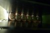
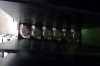
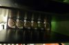
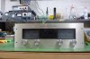
Hey all. I thought I'd post up my journey with a 700B that I pulled out of my father's storage unit after he passed. It was literally going to be recycled but I saw it, recognized the name, liked the build quality and decided to bring it home with me to see what I can do with it. I guess in life it is better to be lucky than good, as I've subsequently found out. I now can't wait to hear how this transistor beast stacks up to my vacuum tube ideals. I keep a very open mind in this regard because I've heard great and terrible out of both camps.
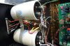
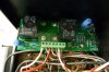
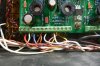
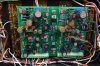
After reading up on various audio forums, I eventually learned of this site, WO driver board, LED board and WA DCP board. I decided it was worth throwing a few hundies at it since my cost basis was nil and to see what it can become, and what I can learn in the process. I thought it wise to put in the DCP board before testing - safety was my intention. I then built the WO kit and installed it.
It didn't work. So, I opened an email dialogue with Joe and no surprise to you guys, his support goes beyond the call of duty. He caught a missing resistor that I though only applied to the full comp build and the biasing transistor term blocks go on the back side of the board. I had some wild voltages in inappropriate places. Joe then sent me his single point grounding schematic and I got busy again.
So, now I think I'm getting closer. When I do the WO biasing procedure, I can't get below 0.500 V, where I should be between 0.300 V and 0.400 V. The WA DCP board checks out, including the low frequency test. Thinking I was good to run a test tone through speakers, when I powered it up with speakers attached, a really unpleasant noise came out. It sounds like an alarm clock buzzer and about as loud. It comes out of both channels with equal volume and tone. The volume control does not increase or decrease the noise. If I put a 1kHz tone into it and turn up the input voltage, it eventually starts to drown out the buzzing but not entirely.
Any ideas on where I can start troubleshooting?
A little more background. I did things in the wrong order. I didn't test out the unit before upgrading - bad on me. I did test all the NEC output transistors and they tested good (new MJ21196 and RCA410 drivers on the way from Joe though). I tested the biasing transistors and they tested good. I double checked the wiring of the WO PL14_20 board, and I think it is solid but nothing is above verifying.
About my skills - I have a Fluke scopemeter, freq generator, Variac, dim bulb tester, variable AC power supply, meter, Peak transistor tester and Peak capacitor tester. My knowledge and skills are definitely amateur but I listen, follow direction pretty well and have a desire to learn. And a now burning desire to get this amp right.
Any thoughts (other than sell it to me for $200 and cut your losses, fool)
-Steve
 ).
).