Power transistor help

gary33030

Journeyman
Joined
Aug 28, 2022
Messages
85
Location
Homestead, Florida 33035
Tagline
I've had Phase Linear before!
#1
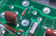
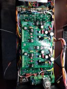
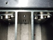
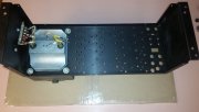
I purchased a Phase Liners 400 Series II off the internet. I purchased all parts and boards from White Oak. I've been building since Aug. All has gone well, the electrical testing is good, I'm up to installing first row of transistors. I've resisted using a hammer as Mark 5W8Comer suggested in his videos.

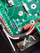
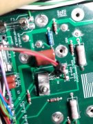
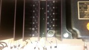
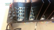
When I get the transistor line up and push down, it feels lick so little of the pin is making contact. I've done my electrical test with first row installed. All is well, but I feel as if I'm not making contact with the pins of the transistors, and they are not in the circuit. How far should they push in once lined up? How can you tell if there in the circuit?

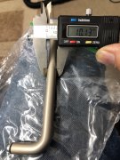
Also on another note, I purchase Joe's 400 face plate. What does everyone do for the handles?
 

George S.

Veteran and General Yakker
Joined
Feb 18, 2020
Messages
4,580
#2
Are the pins visible and protruding from the gold cups when looking at the backplanes? The Series 1 has thin heatsinks and the pins are very visible. The cast Series 2 heatsinks are thicker, and not much of the pin is visible. You should be able to look in the gold cups hole and see the pin.
Hopefully the gold cups are on the correct side of the board.
And, you are using the thin silpad insulators and not mica?
Others have commented on similar issues with the cast heat sinks, but it's a non issue. Download the transistors datasheet and do continuity checks using the transistors case and gold cups.
 

Vintage 700b

Chief Journeyman
Joined
Mar 13, 2019
Messages
751
Location
Wisconsin
Tagline
Fabricator
#3
Welcome aboard gary33030.
Installing the transistors is a delicate dance, especially on your first amp. Take your time !
There should be NO need to force the pins, and you mention that you purchased ALL
boards, meaning the backplane boards as well. Check the alignment carefully. The clearance
on the fins (8 or 4 fin ?) needs to be looked at closely as well, before even thinking of installing the transistors.
Correctly lined up, the transistor will gently push into the sockets, and seat on the Sil-Pad. It is a very positive
engagement, no forcing, and as I said, if the sockets have been correctly soldered into the backplanes, and the
chassis holes are centered, along with the fin holes, it is a very easy "push" home. It can be a bit frustrating on your first
build, but I cannot emphasize taking it slowly, check and recheck. Keep your eye on the prize here. Extra time spent checking
and gently assembling will pay off huge in the end. A correctly WOPL'd 400/700 is amazing, and will reward you every day once
you get everything assembled correctly.
Hopefully you are following the "Bring up Sheet" included with the kits that you purchased. Joe covers all the bases
on electrical testing in his documentation.....follow it to the letter.
The handles if you want them (many amplifiers were assembled without them) are often available from people parting out
old amps. Read the threads that Gene French posted, for some help. Gene may chime in here, but he used some beautiful
after market handles on his 400's.
Good luck with your project, again do not rush your assembly. When the transistor pushes into the sockets correctly it is a very satisfying thing !!!
 

George S.

Veteran and General Yakker
Joined
Feb 18, 2020
Messages
4,580
#5
And I said "continuity check". Better if I had said to check the transistor using the diode setting on the multimeter, using the gold cups rather than the leads. I'd check with only one installed.
 

gene french

Veteran and General Yakker
Joined
Mar 6, 2022
Messages
5,152
Location
guayabo de bagaces, guanacaste, costa rica....
Tagline
music...the healer of souls...
#6
Welcome aboard gary33030.
Installing the transistors is a delicate dance, especially on your first amp. Take your time !
There should be NO need to force the pins, and you mention that you purchased ALL
boards, meaning the backplane boards as well. Check the alignment carefully. The clearance
on the fins (8 or 4 fin ?) needs to be looked at closely as well, before even thinking of installing the transistors.
Correctly lined up, the transistor will gently push into the sockets, and seat on the Sil-Pad. It is a very positive
engagement, no forcing, and as I said, if the sockets have been correctly soldered into the backplanes, and the
chassis holes are centered, along with the fin holes, it is a very easy "push" home. It can be a bit frustrating on your first
build, but I cannot emphasize taking it slowly, check and recheck. Keep your eye on the prize here. Extra time spent checking
and gently assembling will pay off huge in the end. A correctly WOPL'd 400/700 is amazing, and will reward you every day once
you get everything assembled correctly.
Hopefully you are following the "Bring up Sheet" included with the kits that you purchased. Joe covers all the bases
on electrical testing in his documentation.....follow it to the letter.
The handles if you want them (many amplifiers were assembled without them) are often available from people parting out
old amps. Read the threads that Gene French posted, for some help. Gene may chime in here, but he used some beautiful
after market handles on his 400's.
Good luck with your project, again do not rush your assembly. When the transistor pushes into the sockets correctly it is a very satisfying thing !!!
i cant take credit for the handles...mr george thought of this one...and yes, they are beautiful...
 

Attachments

Gepetto

Administrator
Staff member
Joined
May 15, 2011
Messages
13,530
Location
Sterling, MA
Tagline
Old 'Arn Enthusiast
#12
Gary, when you get the transistors seated properly, you should see the B-E leads protruding through the sockets like this picture shows. It takes some patience to get the leads lined up to the socket holes, not much lead in provided unfortunately. When you do find home, you will see that they drop in easily. The magnetic mechanics tool is the easiest method as the pictures in the instructions show. Brush up on those working in the dark skills we all used to have... :)


1670693709740.png
 

gary33030

Journeyman
Joined
Aug 28, 2022
Messages
85
Location
Homestead, Florida 33035
Tagline
I've had Phase Linear before!
#13
Joe,
My pins do not come through the sockets. I can feel them aligned and they push down without force (or hammer) They don't even push out the solder plugs. As one person pointed out, maybe I've soldered on the wrong side of the board. I've checked and rechecked, I feel I'm good. I not sure how to check electrically. So close to the end....
 

Attachments

e30m3mon

Chief Journeyman
Joined
Feb 9, 2013
Messages
872
Location
Hudson Valley NY
Tagline
---
#14
What does everyone do for the handles?
There is a guy selling PL handle reproductions. They fit the 5" center mounting holes and the finish is pretty close to the original "champagne" color. Unfortunately the diameter of the metal is a little larger than the original and does not fit the ferrules.

If you don’t have the ferrules and don't care, these handles might be just fine for you. I can make a set of (2) handles available for you for a sweet deal.
 

Attachments

Gepetto

Administrator
Staff member
Joined
May 15, 2011
Messages
13,530
Location
Sterling, MA
Tagline
Old 'Arn Enthusiast
#15
Joe,
My pins do not come through the sockets. I can feel them aligned and they push down without force (or hammer) They don't even push out the solder plugs. As one person pointed out, maybe I've soldered on the wrong side of the board. I've checked and rechecked, I feel I'm good. I not sure how to check electrically. So close to the end....
SInce you are done with the soldering to the backplane, use a straight resistor lead to push out the OFP plugs from the heatsink side. You should then be able to see the ends of the transistor leads in the socket.
 

George S.

Veteran and General Yakker
Joined
Feb 18, 2020
Messages
4,580
#16
Those are the thick heatsinks. Pins won't protrude out of the solder cups. Do as Joe says. Everything is good!
I built a similar 400 S2 couple years back, same deal, works excellent.
I remember Sniff built his first 400 S2 awhile back and kinda freaked with same issue. The contacts are inside the cup. Hopefully Sniff will comment.
 

WOPL Sniffer

Veteran and General Yakker
Joined
Aug 10, 2015
Messages
11,226
Location
Minnie-Soda
Tagline
Screw it
#18
Those are the thick heatsinks. Pins won't protrude out of the solder cups. Do as Joe says. Everything is good!
I built a similar 400 S2 couple years back, same deal, works excellent.
I remember Sniff built his first 400 S2 awhile back and kinda freaked with same issue. The contacts are inside the cup. Hopefully Sniff will comment.

My pins came through, just barely though. His Pems are sticking up and not in flat. Time to disassemble.
 

WOPL Sniffer

Veteran and General Yakker
Joined
Aug 10, 2015
Messages
11,226
Location
Minnie-Soda
Tagline
Screw it
#19
Joe,
My pins do not come through the sockets. I can feel them aligned and they push down without force (or hammer) They don't even push out the solder plugs. As one person pointed out, maybe I've soldered on the wrong side of the board. I've checked and rechecked, I feel I'm good. I not sure how to check electrically. So close to the end....

If you zoom in on the first pic, you can see the PEM's are not all the way flush.
 
Top