Hoping someone can help me with this as I spent all week looking at this and can't solve it. With the preamp on, the LED never lights, otherwise all functions work and sounds great.
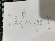
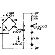
I don't understand why they used 2 legs of a transistor, the LED, and put it between B+ and B-.
Since the Ground, B+, B- "rails" run directly along the front of the board right beside this circuit, I'm thinking I just going to rewire the LED between the ground and B+ with the appropriate voltage dropping resistor for the LED which is simple to calculate.
And, yeah, the LED is good, pulled it and powered it up with a little breadboard variable power supply, bright at 2.5 VDC.
What do you all think?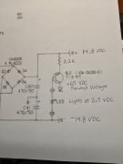