I recently acquired one in need of repair and need some guidance. With a DBT in circuit turned power on bulb not dim but not very bright. I removed all outputs and found 1 that was bad. reinstalled 6 good transistors. The r and l amps board had 1 burnt resistor and several others that had been very hot at one time r213 was burned badly. I also replaced other components that had gotten very hot R213, r113, r 115, r215, r103, r203,. After this hooked up cd and no movement from left or right LED gain knobs. Actually right gain knob LED illumination is stuck in the middle. Ideas thanks.

PL D500
- Thread starter vmaxman
- Start date
I recently acquired one in need of repair and need some guidance. With a DBT in circuit turned power on bulb not dim but not very bright. I removed all outputs and found 1 that was bad. reinstalled 6 good transistors. The r and l amps board had 1 burnt resistor and several others that had been very hot at one time r213 was burned badly. I also replaced other components that had gotten very hot R213, r113, r 115, r215, r103, r203,. After this hooked up cd and no movement from left or right LED gain knobs. Actually right gain knob LED illumination is stuck in the middle. Ideas thanks.
Ed
- Joined
- Jan 14, 2011
- Messages
- 74,216
- Location
- Gillette, Wyo.
- Tagline
- Halfbiass...Electron Herder and Backass Woof
The high temp light and high frequency lights are both illuminated would this indicate where the issue might be? thanks
If the three plugs of small wires on the back top of the display board are mixed up you can have this issue however not a common thing.
when engaged the high frequency circuit cuts input to the opamps when high frequency oscialtion detected so you need to sort out the high frequency problems. You can pull c105 c205 and c1 c2 from board to remove circuit from system also pull D5 to turn off light. It is proabley the ic that is gone south on you there.
As to high temp that light doubles as indicator for DCP relay as well. When first powered on it lights and then goes out when relay latches. If relay does not latch light stays on and there is no output. The wires to engage the relay may be not connected or Loose. I will attach photo of relay
this unit requires some test equipment and the service manual. Pm me your email address if you need a copy
glen
Attachments
-
 20.1 KB Views: 25
 -
 20.3 KB Views: 32
 -
 7.4 KB Views: 51
Schematic are on post 1 of this thread
http://forums.phxaudiotape.com/showthread.php/6202-Phase-Linear-Dual-500-schematics
http://forums.phxaudiotape.com/showthread.php/6202-Phase-Linear-Dual-500-schematics
- Joined
- Jan 14, 2011
- Messages
- 74,216
- Location
- Gillette, Wyo.
- Tagline
- Halfbiass...Electron Herder and Backass Woof
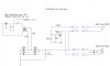
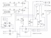
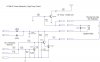
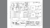
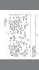
More re-drawn D500 schematics. I'm working on the rest of the LED meter(s) and control section next. I can't believe PL (attempted to) squeeze the entire schematic on one lousy page and made the print so small.
View attachment Phase Linear D500_Left Channel Input_High Frequency Circuit_v1.0_081717.pdf View attachment Phase Linear D500_Right Channel Input_v1.0_081717.pdf
View attachment Phase Linear D500_Left Channel Input_High Frequency Circuit_v1.0_081717.pdf View attachment Phase Linear D500_Right Channel Input_v1.0_081717.pdf
Wanted to revive an old thread, hope you guys OK with it.
Thanks THD+N for the updated Schematics for the D500. Appreciate the hard work.
But I have to ask, since I wanted to work on my LED meters over the next few weeks.
Did you ever finish your updated rendition of the LED meter control section??
Carl
Thanks THD+N for the updated Schematics for the D500. Appreciate the hard work.
But I have to ask, since I wanted to work on my LED meters over the next few weeks.
Did you ever finish your updated rendition of the LED meter control section??
Carl
No all my LED drivers are still working.
But,, I am being a little picky here.
On my Dual 500 the left meter when the volume is turned all or most of the the way down, the far leftmost LED is not moving or lighting as far left as it should.
I believe it is the 3rd LED that is lighting up when idle, maybe the 2nd LED.
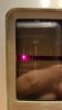
Here have a look , the left LED indicator doesn't drop all the way back to the leftmost position.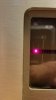 Here's the right side, its ok.
But,, I am being a little picky here.
On my Dual 500 the left meter when the volume is turned all or most of the the way down, the far leftmost LED is not moving or lighting as far left as it should.
I believe it is the 3rd LED that is lighting up when idle, maybe the 2nd LED.
Here have a look , the left LED indicator doesn't drop all the way back to the leftmost position.
Here's the right side, its ok.
It may be just an alignment issue and not the LED or the drivers at all. The more I look at it, the more it looks as if the number plate is shifted to the left.
One of the reasons I was looking for an updated schematic is this amp will turn-on normally, but once it has warmed up for 10 min or more and I turn it off, then attempt to turn it back on all it does is hum. It has to cool for about a half hour then to will turn on normally. At least until it heats back up.
One of the reasons I was looking for an updated schematic is this amp will turn-on normally, but once it has warmed up for 10 min or more and I turn it off, then attempt to turn it back on all it does is hum. It has to cool for about a half hour then to will turn on normally. At least until it heats back up.
Last edited: