Pioneer SX-880 resurrection

J!m

Veteran and General Yakker
Joined
Dec 24, 2019
Messages
9,375
Location
Connecticut
Tagline
BOT
#1
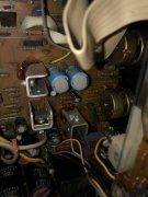
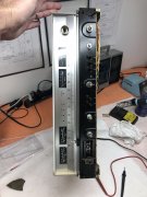
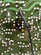
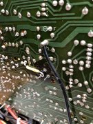
Here are the “before” pictures:

2FFC7903-333F-4833-BE39-941644761A6B.jpeg 5F982391-90BB-40FD-84AA-823DB4ECE768.jpeg 502C71E9-AAC2-450E-AA45-D07E57501AF3.jpeg 7E843655-BA0D-4C38-B378-2EC3E0BE1867.jpeg 6ABEFCDB-01FE-405B-8BD1-0A1B4823FA84.jpeg 0A2C0F11-A190-43B2-B4F1-718E11CD8D82.jpeg

0E01BBBF-9D88-4FAA-83C0-D4F8E1BE8155.jpeg 983A9353-25F0-426B-B0AA-CCBB9F712179.jpeg B34A7E49-F5BC-4928-9560-3D75ECE6C01C.jpeg 86591810-D871-4CD6-A5FD-E8886093E82F.jpeg

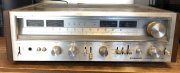
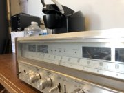
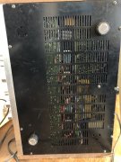
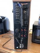
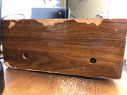
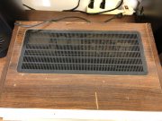
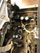
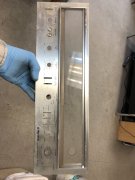
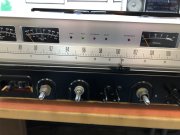
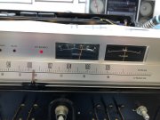
Pioneer SX-880 that was (at best) used as a garage system. I shudder to think what this poor thing has endured…

Im gonna put some shine on it and feed it some fresh electrons.

Missing two feet, the power switch cover and a side screw for the wooden case. That I know of… if anyone has something in their junk box, please let me know.

Sit back and enjoy laughing at me trying to fix this thing up!

We now return you to your regularly scheduled programming.

—————————————————-
 
Last edited:

J!m

Veteran and General Yakker
Joined
Dec 24, 2019
Messages
9,375
Location
Connecticut
Tagline
BOT
#3
Today I did more cleaning. I don’t think it will end within my lifetime, but I keep at it.

Before:
BE53B68B-572B-405A-A7AC-0A6E91408033.jpeg 7286C51C-DBCC-4D82-8E05-91B13A3EE528.jpeg

Knobs now have about eight hours in ultrasonic and another 12 just soaking. After that I did the surfaces with acetone. Still dirty…

B02B2D8A-E4B8-4AF9-88CE-4B2CF2D97EDA.jpeg

You can really see it on the big tuning knob. Then I tried the cleaner we use on the compressor blades for P&W…

6D339782-D913-4B29-BD0D-BCC5AE20C1B1.jpeg

Maybe you don’t see it, but that did the trick. Amazing how much dark brown still came off after alcohol ultrasonic and acetone!

I also went for the voltage regulator. There is precisely zero room to get in there and work. And a pair of caps directly in the way.

B335EA93-DB87-42C0-833E-8403628AE54E.jpeg
So I did. I took the bit out of my stubby Klein screwdriver and slid it into a 1/4” box end wrench. That worked. Eventually.

I got a new much larger heat sink at the local place, (have I mentioned the place is great?) along with thermal paste. Cut down a 4-40 screw and then realized I have no hope of accomplishing this. Then I did.

Doing that, I noticed it felt like the regulator was loose. Moving it gently and observing the other side I could see a leg moving… I added some flux, top and bottom of the board, got it nice and hot and added a bit of fresh solder for good measure. Once done, I confirmed continuity to the next exposed pin, following the traces from each leg. Good. And much more solid than before.

I washed down the boards, but they’ll need another can or two, plus the toothbrush. Not looking forward to brushing my teeth with it after this…

Other than a deep clean of the dial, that was it for today. Oh, I broke the power switch straightening the “S” bend from the arm. That sucked, but I have a correct (multi-voltage) replacement on the way
 
Last edited:

J!m

Veteran and General Yakker
Joined
Dec 24, 2019
Messages
9,375
Location
Connecticut
Tagline
BOT
#6
I use the CRC “plastic safe” electrical cleaner from Home Depot. The other stuff works better but it strips the paint off your car at ten paces. Melts just about every type of plastic too.
 

J!m

Veteran and General Yakker
Joined
Dec 24, 2019
Messages
9,375
Location
Connecticut
Tagline
BOT
#8
I don’t like to touch the dial but I didn’t have a choice today.

On the 580, I used a soft paintbrush. A good natural bristle one I use on models and props.

On this, I started with q-tips soaked in the P&W cleaner (MC Spray & Wipe) and they came out BLACK. Okay, I need to clean the dial. Cotton cloth damp with the spray & wipe and gently wipe. Q-tips in the corners and on the pointer- VERY GENTLE!! Edit- always wip in a single pass in the “brush” direction of the metal. Never scrub back and forth or in circles. One scratch against the “grain” will ruin it.

Looks good now.

image.jpg

Always finish with the brush to get the last bits of lint out.
 
Last edited:

J!m

Veteran and General Yakker
Joined
Dec 24, 2019
Messages
9,375
Location
Connecticut
Tagline
BOT
#9
Powered it up and no smoke!
But not much else either...

Decided to check that regulator first, and I have correct voltage on one side, and nothing on the other. Going to pull it now, after all my gymnastics to put the heatsink on it, and figure out a replacement for it. The number in the parts list comes up non-existent in Mouser (not surprising). But, that may be an internal Pioneer number too, so I'll cross it once I have it out.

95598E4E-D84A-42F8-8395-351D9C22C0F2.jpeg

Now, it’s out!
 
Last edited:

J!m

Veteran and General Yakker
Joined
Dec 24, 2019
Messages
9,375
Location
Connecticut
Tagline
BOT
#11
Apparently not. Sold as a parts unit.

A pad lifted (or I just finished it off) so I made a new one…

781AD89B-45EF-42DA-B9FF-EE1F6D42166A.jpeg A6F797CC-E01C-4131-85CD-AE466019726B.jpeg 89E39B44-4B44-47D4-B5A5-CCBC1E8AB819.jpeg
I had checked continuity of all three connections before power up so it wasn’t broken before.

I have voltage at the output devices so I think this 15V regulator is for all the low voltage everything after it. Even the LED indicators don’t light, and with no output the other voltage regulators have 0V.

Im somewhat confident this replacement will get it 100% operational.
 

J!m

Veteran and General Yakker
Joined
Dec 24, 2019
Messages
9,375
Location
Connecticut
Tagline
BOT
#12
And, for less than $9 my local place had an NTE379 in stock. I should have this running later today- have to spray some samples first.

I should point out: the original was EGC379 and the modern NTE brand is NTE379. Specs match; no idea where it’s made. It came with a mica pad and nylon step washer, which I’ll save for later.
 
Last edited:

J!m

Veteran and General Yakker
Joined
Dec 24, 2019
Messages
9,375
Location
Connecticut
Tagline
BOT
#13
Progress!

installed the new part:

1FEE2326-854C-4A19-9125-8BE9839BCA57.jpeg BF24FF55-1363-4ACC-B646-013226E695B0.jpeg

Now I have the relay click at turn-on, as well as the FM light. Tuning indicator is moving as well, as I pass stations. No signal strength and no stereo light since I don’t have an antenna in it.
3169B2D8-EF5B-4F7B-A801-0C1B23575602.jpeg

I’m going to let it cook for a bit and then set bias. I’ll find a roll of wire to make an antenna too.
 

J!m

Veteran and General Yakker
Joined
Dec 24, 2019
Messages
9,375
Location
Connecticut
Tagline
BOT
#15
Bias and idle current set. It wasn’t too far off but now it’s within a millivolt of optimal (30mV) for both.

We are go for headphones!

EDIT- headphone test passed! Power meters dance when we turn it up.

PS: that new heat sink is HOT. I’m going to get a temp off it before I shut ‘er down.
Bottom line: less that $10 for the regulator got it working.
 
Last edited:

George S.

Veteran and General Yakker
Joined
Feb 18, 2020
Messages
4,585
#17
Progress!

installed the new part:

View attachment 59520 View attachment 59521

Now I have the relay click at turn-on, as well as the FM light. Tuning indicator is moving as well, as I pass stations. No signal strength and no stereo light since I don’t have an antenna in it.
View attachment 59522

I’m going to let it cook for a bit and then set bias. I’ll find a roll of wire to make an antenna too.
Good job on repairing that trace! Well worth fixing crispy traces to repair a machine.
 

J!m

Veteran and General Yakker
Joined
Dec 24, 2019
Messages
9,375
Location
Connecticut
Tagline
BOT
#18
It was passing current during the initial test but it gave up when I pulled the part out.

Solder sucker worked great but that pad was torn- probably from the part rocking around for however long.

Not sure I mentioned it but the transformer was loose too. Two of the nuts were barely on the screws. As a matter of course I checked every screw. Most were tight enough but a few were loose.
 

J!m

Veteran and General Yakker
Joined
Dec 24, 2019
Messages
9,375
Location
Connecticut
Tagline
BOT
#20
Yeah, I haven’t heard back from Jer about editing the old ones but I can add more “before” pictures above… (done)

I also scrubbed the wooden case and started on the face plate, but ran out of time. (No pictures- just work). If I hadn’t broken the power switch arm I could have got the front and bottom on.

I’ll do it next year.
 
Last edited:
Top