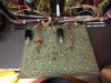
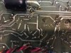
Someone had asked me a little while ago to post some pictures of the various PC boards used in the Phase Linear 700B.
(See attached photos saved as pdf's)
The revision history is as follows:
1.) PL14A Ser. #673-000 (June 1973) through 474-200 (May 1974 unit 200)
2.) PL14B (My best guess at this time is that this version was only used for a few months from late May 1974 until approx. November 1974.)
3.) PL20A
4.) PL20B
5.) PL20 (serial number? until serial number 7000? in late 1977 or early 1978?)
Yes that is right the PL20 came out last!
The only pc board that is completely un-restored (in the attached photos) is the PL14B pc board.
NOTE: The PL14A pc board was a universal board also used in the Phase Linear 400 series 1 amp with a few changes. Phase Linear also had a PL14B board they used in their 400 series 1 amplifier. However the PL14B used in the 400 is the smaller in size like that of the PL14A.
Here are a few of the differences between a PL14A used on a 400 and a PL14A used on a 700B:
1.) R7 330K (400) 360K (700B)
2.) R8 100K (400) 120K (700B)?
3.) R19 470 (400) 680 (700B)
4.) R24 3.3K (400) 5.6K (700B)
5.) R25 3.3K (400) 5.6K (700B)
6.) R28 5.6K (400) 7.5K (700B)
7.) R29 5.6K (400) 7.5K (700B)
added 6.8K resistor in series between R7 and D1 and D2 on 700B
8.) C1 220pF (400) 330pF (700B)?
9.) C3 22/100 (400) 47/100 (700B)
10.) Q5 40327 (400) 40412V1 (700B)
I sure would love to see a prototype PL14A, PL14B or PL20A pc board. As you may have noticed there are a lot of unused holes on the PL14A, PL14B and PL20A pc board. My guess is that they made some minor modifications after the PL14A and didn't get around to changing the artwork until the PL20B came out. They may also have had some DC offset trim-pots like that of the earlier PL0171 (700 series 1 amps) and PL400C (400 series 1 amps) on at least one version of these earlier pc boards.
PL14B and PL20A had R63 on the back of the pc board. R63 was re-located to the top of the pc board with the PL20B and subsequent PL20 revision.
C5 was .0015 and was changed to .0018.
PL14B R24 and R25 5.6K 1 watt resistors were replaced with 5.6K 1/2 watt resistors with PL20A.
PL14B R28 and R29 7.5K 1 watt resistors were replaced with 7.5K 1./2 watt resistors with PL20A.
There were a number of other parts changes not noted in the service manual as there are no schematics (for the PL14B) to refer to. I will get to them eventually
I have replaced in most cases any carbon composition resistors with carbon film resistors on these pc boards. Some of the 40327 pre-driver transistors have been replaced with 2N3440's.
All of my pc boards (as shown in photos) now have the protection circuit modification installed (per service bulletin 7721) to prevent severe high frequency oscillations when performing the short circuit test. This modification involves the following:
1.) Desolder C17 (.05 mf ceramic disc capacitor) and discard.
2.) Obtain a 130 ohm 1/2 watt resistor and a .005 (or .0047)/100 v capacitor.
3.) Solder the series RC network across the base-collector junction of Q9 (2N1305) on the foil side of the PC board....
NOTE: In some cases with the PL20A pc board the 130 watt resistor is located on the top of the pc board and the capacitor is soldered to the bottom side. You will notice with the last PL20 pc (with the silk-screening on the top) that the RC network was already included.
As more details come to mind, I will revise the text in this post.
If anyone has any used Phase Linear pc boards (regardless of condition) they no longer want and are willing to donate to my collection, please contact me. I am also interested in any old Phase Linear transistors as well, as I am also collecting some data I hope to post in the future about transistor testing.
Ed
Attachments
-
1.9 MB Views: 68
-
2.5 MB Views: 35
-
1.9 MB Views: 67
-
2.3 MB Views: 32
-
1.5 MB Views: 41
-
2.4 MB Views: 29
-
2.3 MB Views: 33
-
1.9 MB Views: 29
-
2.3 MB Views: 32
-
2.6 MB Views: 27
-
2.4 MB Views: 37
-
2.4 MB Views: 36
Last edited: