Hello George,
I personally am not a member of Facebook. Why not post the details of your build here on Phoenix?
Many of us are Phase Linear addicts, and especially WOPL modified Phase Linear amplifiers.
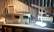
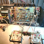
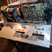
Your early 700 has it's own set of challenges that we don't often see, and all of us enjoy following a challenging build, with lot's of pictures!
I was able to read the text that you submitted on the Facebook posting, and disagree with you giving credit to " David Carver...a 25 year old engineering kid"....starting Phase Linear. It was Bob Carver, see below. Just a tiny bit of the "Bob Carver Legacy".
There are many experts and a few ex-employees of Phase Linear on this forum, so they may step in, however having owned these components myself for over 47 years, I offer the following:
Bob Carver started Phase Linear in his home in Richmond Heights, Edmonds area, north of Seattle, WA in about mid-1969.
Phase Linear was founded by Bob Carver in 1970.
With the help of Carver's partners Steve Johnston and Jack Goodfellow, Phase Linear was launched in 1970 in a small building at 405 Howell Way in Edmonds, Washington.
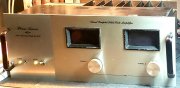
The first component to be manufactured was the model 700 power amplifier, with 350 watts per channel.
1970 to 1973 model 700
700b debuted in August of 1973.
Bob Carver left Phase Linear in late 1977.
Carver Corporation launched in 1978.
J.P. Van Meter joined Phase Linear in 1974, bringing with him his design experience working at Macintosh and University Sound. When Carver left Phase Linear in 1977, Van Meter became the Chief Design Engineer and the Engineering Manager. Under his direction the Series II models were designed and built, and introduced in 1978.
700 Series II introduced in 1978.