First I want to thank Mark for sharing the part# and showing this is possible. The part# is Mouser 693-6100.4115
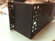
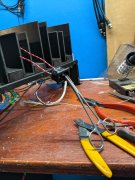
First thing I did was measure the socket and made a accurate to-scale drawing and stencil of the opening I needed cut on the chassis. I glued the stencil with rubber cement onto the chassis exactly where I wanted the new hole. Then drilled small holes just inside the edge of the stencil all around the edge, but being careful to keep it slightly undersize at this point. Took the stencil off then, and added a couple more small holes between the edge and the Heyco hole. With a little careful flexing with pliers, the pieces broke out nicely. Hand filing quickly gave me the finished shape.
Couple points. Make sure there are no burrs on the inside of the hole edge as they could keep the socket from snapping in. Also, the socket is rather "minimalist" and thin plastic. Mark, I think, stated in a very old post to glue it in with JB Weld. Great idea, so I did so. I coated the sides before pushing it in. The plug is such thin plastic that the epoxy really strengthens it, and it's never coming out by accident. Once you get the plug in, immediately wipe off the excess on the outside of the amp, then flip the amp over onto its heatsinks so the still fluid epoxy will flow against the chassis and make a nice fillet. Just be aware that before it sets there will be a little inside the plug well, easily scraped out with a small screwdriver.
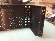
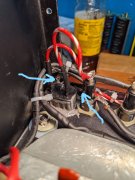
Now a couple BIG points. Install the socket with the safety ground lug UP! The reason for this is two chassis screws that I point out in a photo. Put a hemostat, your favorite soldering heat sink, or roach clip on the socket lugs before you solder, and keep the heat on the wire as much as possible, or the socket will melt, it's very thin plastic. So solder your wiring on, JB Weld it, insert it.
How you wire it is up to you. Mark promotes a totally modern safety grounded hook up, and I get the reasons. But I'm keeping the two wire system of line(goes directly to main fuse, don't screw this up) and neutral, with nothing hooked to the safety ground lug of the IEC socket. There are proponents of each system on this forum, search and read why.
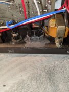
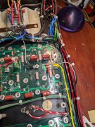
So why upgrade to a IEC plug? 15 Amp rated socket, 14 AWG 300V cord, the convenience of unplugging at the amp. This replaces the table lamp sized power cord and Heyco. If you decide to do the mod, check out the candy cane colored red and white wire in the photos. Went from the stock WOPL 16 AWG to 14, same as the new power cord. 14 AWG just fits the solder lug holes of the thermal breaker. HAVE FUN!!!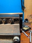
First thing I did was measure the socket and made a accurate to-scale drawing and stencil of the opening I needed cut on the chassis. I glued the stencil with rubber cement onto the chassis exactly where I wanted the new hole. Then drilled small holes just inside the edge of the stencil all around the edge, but being careful to keep it slightly undersize at this point. Took the stencil off then, and added a couple more small holes between the edge and the Heyco hole. With a little careful flexing with pliers, the pieces broke out nicely. Hand filing quickly gave me the finished shape.
Couple points. Make sure there are no burrs on the inside of the hole edge as they could keep the socket from snapping in. Also, the socket is rather "minimalist" and thin plastic. Mark, I think, stated in a very old post to glue it in with JB Weld. Great idea, so I did so. I coated the sides before pushing it in. The plug is such thin plastic that the epoxy really strengthens it, and it's never coming out by accident. Once you get the plug in, immediately wipe off the excess on the outside of the amp, then flip the amp over onto its heatsinks so the still fluid epoxy will flow against the chassis and make a nice fillet. Just be aware that before it sets there will be a little inside the plug well, easily scraped out with a small screwdriver.
Now a couple BIG points. Install the socket with the safety ground lug UP! The reason for this is two chassis screws that I point out in a photo. Put a hemostat, your favorite soldering heat sink, or roach clip on the socket lugs before you solder, and keep the heat on the wire as much as possible, or the socket will melt, it's very thin plastic. So solder your wiring on, JB Weld it, insert it.
How you wire it is up to you. Mark promotes a totally modern safety grounded hook up, and I get the reasons. But I'm keeping the two wire system of line(goes directly to main fuse, don't screw this up) and neutral, with nothing hooked to the safety ground lug of the IEC socket. There are proponents of each system on this forum, search and read why.
So why upgrade to a IEC plug? 15 Amp rated socket, 14 AWG 300V cord, the convenience of unplugging at the amp. This replaces the table lamp sized power cord and Heyco. If you decide to do the mod, check out the candy cane colored red and white wire in the photos. Went from the stock WOPL 16 AWG to 14, same as the new power cord. 14 AWG just fits the solder lug holes of the thermal breaker. HAVE FUN!!!
Last edited: