HF loss - general

Alex SE

Journeyman
Joined
Oct 10, 2021
Messages
251
Location
Sweden
Tagline
Amateur
#1
Hi everybody,
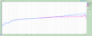
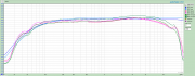
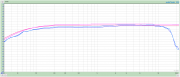
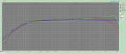
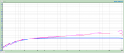
Have a deck that have a roll off at 8kHz. We all know that worn heads use to be suspect n.1 but heads on that deck doesn't look bad.
What I'm wondering is, if anything else can make a HF loss, beside heads.

Info about deck:
- it is cleaned and heads are demagnetized and properly adjusted
- it have all new caps and I have replaced them one by one just to be sure that replacement have a same value. All caps are Nichi UPW / UES and Pana FM / FR.
- don't know if there was a problem before re-cap, didn't tested and tried to adjust it before
- have tested to switch rec pcb from one from the other deck and no difference.
- have tested with front from another deck which is good but result is only slightly better and still roll off from 8kHz which make me believe that even if a head is slightly worn, there can be something more.

Would appreciate all ideas you guys have. If we can start from general theory first I'll be happy to go deeper in a subject and a deck model.
 

nakdoc

Chief Journeyman
Joined
May 11, 2011
Messages
619
Location
Nashville, TN Music City
Tagline
highly biased
#2
What model? The first step is to play a pre-recorded music cassette and switch your monitor between stereo and mono. If there is little difference, then you have some sort of record problem. If you hear a big difference, then the head azimuth needs to be set using a test tape.
Is this a 3 head deck?
 

8991XJ

Chief Journeyman
Joined
Oct 8, 2011
Messages
1,128
#3
High frequency is very small on tape. 15,000Hz is between 3.13 microns and 1/1000 of an inch depending on speed. Since you gave us absolutely no information on what pos you are working with we can not help much. But with such a small size constituting the 15kHz frequency, double it for 7.5kHz about the frequency you are having trouble with anything the moves the tape away from contact with the heads can cause the issue. Even SSS binder stuck in the head gap

But at what level are you losing HF response. HF response is measured 20dB down.
 

Alex SE

Journeyman
Joined
Oct 10, 2021
Messages
251
Location
Sweden
Tagline
Amateur
#4
Deck is RS-B965.
Head azimuth/tilt/height are OK, adjusted with Willys WHS300 and ANT test tape.
Here is a test result (source vs tape):
PS Don't care about frequencies below 200Hz, that is about some resistance mismatch between a sound card and a deck.
Blue is source, pink and green are tape
1645813095922.png

And here is result with a front from another 965 (without rec gain/levels/bias re-adjusted) :
Pink is source, blue is tape
1645813203324.png

One more thing, probably worth to mention, I have earlier tried to move those hot Q601 and Q602 from rec pcb and Q610, Q611 and Q624 from a main pcb, to one 50x70mm (aprox. 2"x 3"), to avoid burning of main and rec pcb. When tested, deck sounded muffled so I disconnected new pcb and resoldered transistors where they were from beginning. Thought that It have to be some kind of statics. I'm pretty sure that all transistors was properly turned BUT in the case that I did something wrong, can it be that something is damaged? Some cap, resistor diode... whatsoever. Thinking maybe some filter can eventually damaged.
 

Alex SE

Journeyman
Joined
Oct 10, 2021
Messages
251
Location
Sweden
Tagline
Amateur
#5
Here is one more comparing between one and the other 965.
Blue is source
Green is OK deck
Red is a bad one
As you can see (if you look at picture from this post "green line" and a 2nd one from previous post "blue line", that is a same mech and heads mounted on 2 different decks), mechanic/heads from a good deck gives worse result when mounted to a problematic deck. That is what makes me believe that the problem is somewhere in electronics, not in a heads.
Observe that tape used for test is TDK D (NOS).
All I'm saying is just guessing, you professionals understand whole this thing much better than me.

1645857437914.png
 

A.N.T.

Journeyman
Joined
Aug 21, 2021
Messages
55
Location
Cheshire UK
Tagline
Femtoamp- Volt- and Tape- nut.
#8
It looks like an over-bias if these curves are measured on the deck's own recording. Try to reduce the bias till you get the same level at 10 and 16kHz and than change R95/R96 (use a 20K trimmer) and see what value would give you a flatter overall response.

Cheers

Alex
 

vince666

Chief Journeyman
Joined
May 15, 2013
Messages
979
Location
deep south of Italy
Tagline
I will not be missed! :p
#11
It looks like an over-bias if these curves are measured on the deck's own recording. Try to reduce the bias till you get the same level at 10 and 16kHz and than change R95/R96 (use a 20K trimmer) and see what value would give you a flatter overall response.

Cheers

Alex
Nice tip.

And, please, let me understand a bit...
so R95/96 sort of control the amount of Rec EQ amp boost or something like that?

Cheers,

Vince
 

Alex SE

Journeyman
Joined
Oct 10, 2021
Messages
251
Location
Sweden
Tagline
Amateur
#13
It looks like an over-bias if these curves are measured on the deck's own recording. Try to reduce the bias till you get the same level at 10 and 16kHz and than change R95/R96 (use a 20K trimmer) and see what value would give you a flatter overall response.

Cheers

Alex
Opening a "bad one" (reed line on the last picture) that have a HF loss, now. Will chase 10 and 16kHz. Unsealed new UDII-CD for tests, can be better choice than TDK D.
Be back soon...
 
Last edited:

vince666

Chief Journeyman
Joined
May 15, 2013
Messages
979
Location
deep south of Italy
Tagline
I will not be missed! :p
#15
As far as I remember, that resistor adjusts the HF "shelf" in the recording EQ. Unfortunately I don't have time to measure and illustrate it on a graph at the moment.

Cheers

Alex
Thanks and no worries, Alex.

I get what you mean with adjusting HF "shelf" EQ.
Really useful to know.

Cheers,

Vince
 

Alex SE

Journeyman
Joined
Oct 10, 2021
Messages
251
Location
Sweden
Tagline
Amateur
#17
Here is what I could do:
1645999094584.png
R95 and R96 are regulating frequencies from about 2kHz and up (doesn't affecting frequencies below 2kHz).
As you can see there is some kind of inversion between channels, while "light blue" is lower than "blue" at low frequencies, at high frequencies situation is reverse.
Also, you can see that R95 and R96 are replaced by 5.4 and 7.5k.

Question:
1. Is it OK if, as on picture, at 100Hz it is -30db, at 500Hz -29db, at 1kHz and up is -28db ?

For those who are wondering how sm looks like and where exactly are those R96 and R96 (see yellow mark):

1646000083893.png
 
Last edited:

vince666

Chief Journeyman
Joined
May 15, 2013
Messages
979
Location
deep south of Italy
Tagline
I will not be missed! :p
#18
Here is what I could do:
View attachment 62849
R95 and R96 are regulating frequencies from about 2kHz and up (doesn't affecting frequencies below 2kHz).
As you can see there is some kind of inversion between channels, while "light blue" is lower than "blue" at low frequencies, at high frequencies situation is reverse.
Also, you can see that R95 and R96 are replaced by 5.4 and 7.5k.
Nice.

Anyways... on the "before" plot with 15k resistors on both channels, you still have some bias mismatch between the L and R channels... then you go and compensate for this by putting 2 different values at R95 and R96.

I would try this...
I'd put the same value on both R95 and R96 and I'd go compensating the L / R difference with the internal bias pots, VR301 (Left) and VR302 (Right).
While the fine bias knob at front panel is common for both channels so, to fine tune a L / R mismatch you'd better go on one of the internal trimpots until you make one channels the same as the other one.

Cheers,

Vince
 

Alex SE

Journeyman
Joined
Oct 10, 2021
Messages
251
Location
Sweden
Tagline
Amateur
#19
Nice.

I would try this...
I'd put the same value on both R95 and R96 and I'd go compensating the L / R difference with the internal bias pots, VR301 (Left) and VR302 (Right).
While the fine bias knob at front panel is common for both channels so, to fine tune a L / R mismatch you'd better go on one of the internal trimpots until you make one channels the same as the other one.

Cheers,

Vince
Well Vince, reason for "inversion" between blue and light blue line can easily be wrong bias as you suggest me to adjust. I'll first check resistance on VR301 & VR302 and will write it down.
Will make a pdf file with everything what is done/replaced/modified on my decks. Much easier to work with some device (not only a deck) if the one have a facet in hands. Besides, one day if I decide to sell them, buyer will know a whole history.
Somebody wrote somewhere that it doesn't sounds like good idea to buy a deck that somebody unprofessional has serviced/modified. I don't see a problem if everything done is according to instructions from a trusted professionals like Alex and some other members here.
 

Alex SE

Journeyman
Joined
Oct 10, 2021
Messages
251
Location
Sweden
Tagline
Amateur
#20
It looks like an over-bias if these curves are measured on the deck's own recording. Try to reduce the bias till you get the same level at 10 and 16kHz and than change R95/R96 (use a 20K trimmer) and see what value would give you a flatter overall response.

Cheers

Alex
Thank you for advice Alex. I'm sure that many of us here on forum would be grateful if you could explain what is the reason of such behavior of decks. Is it about a wear of the heads or maybe oxidation of trimpots or degradation of some components. For example, I did total recap on a deck we are talking about and we all know that there is always some tolerances on capacitors and resistors which can lead to some differences in signal. Can something like that be a reason a deck being kind a weird.

One other question, if I replace a heads as we were talking earlier, will I need to go thru same adjustments as I did now?
 
Top