Customer's PL400 WOPL Upgrade is a Repair

mlucitt

Veteran and General Yakker
Joined
Jun 24, 2011
Messages
3,373
Location
Jacksonville, FL
#1
Got a 1973 PL400 for a WOPL upgrade and then I found these "tweeks" that the owner forgot to mention:
Does this mean we have a problem?
Johnny PL400 Burnt Fuses.jpg

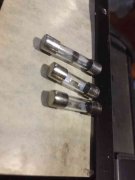
How long do PS caps last in this configuration?
Johnny PL400 Caps.jpg

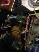
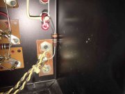
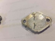
Notice the driver transistor on the left, it let some smoke out from under the mica...
Johnny PL400 Burnt Output Transistor.jpg

Dang, a PL400C2 control board, now I have to drill a hole in the chassis for the WOPL Control Board.
Johnny PL400 PL400C2 Board.jpg

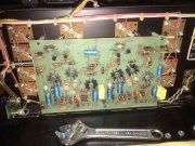
Lots of work and I have not even got to the WOPL part yet...
 

wattsabundant

Chief Journeyman
Joined
Apr 26, 2011
Messages
848
Location
Central Ohio
#4
I'm guessing the AGX fuses are 5 amp and someone was doing full load testing with them. So they opened due to overload and not due to output failure. Output transistor failure is when the fuse element gets deposited on the glass due to arcing. AGX fuses are actually misapplied as they do not have a DC voltage rating. Only AC. Same with AGC fuses. ABC fuses do have a DC voltage rating. I attached the AGX data sheet.

Maybe it's the lighting, but the cap boards look like they were soldered with acid flux/ plumbers solder. I've got a 400 on the bench right now with this version of the rectifier. I used similar cap mounting clamps, but sure didn't try to glue them in. The clamps I used were the proper diameter.

The 0.1 ohm resistor on the ground bus will go away when you install the accepted grounding scheme.

Per the manual the Senistron outputs were only used on this vintage amp.
 

Attachments

orange

Veteran and General Yakker
Joined
Jul 6, 2010
Messages
17,704
Tagline
Broken beyond repair but highly affable
#5
That amp must have been here:

1586420994833.png
 

Gepetto

Administrator
Staff member
Joined
May 15, 2011
Messages
13,553
Location
Sterling, MA
Tagline
Old 'Arn Enthusiast
#6
The proper 40mm cap clamps are provided in the cap kit but the buyer obviously chose not to use them, liked RTV glue better.

All cap kits are soldered with Kester 44 solder when assembled, followed up by flux cleaning, so it is the lighting.
 

mlucitt

Veteran and General Yakker
Joined
Jun 24, 2011
Messages
3,373
Location
Jacksonville, FL
#7
I'm guessing the AGX fuses are 5 amp and someone was doing full load testing with them. So they opened due to overload and not due to output failure. Output transistor failure is when the fuse element gets deposited on the glass due to arcing. AGX fuses are actually misapplied as they do not have a DC voltage rating. Only AC. Same with AGC fuses. ABC fuses do have a DC voltage rating. I attached the AGX data sheet.
Thanks for that document.
The AC fuse was Buss AGC 8, the DC fuses were both Littlefuse 8AS 32V. Remember one bulk capacitor was in backwards... (see post #1)
This is one of the drivers, notice the crack in the mica at the failure point, another driver tested bad (transistor tester said it was two resistors):
Bad Mica.jpg
 

mlucitt

Veteran and General Yakker
Joined
Jun 24, 2011
Messages
3,373
Location
Jacksonville, FL
#8
The good news is the main capacitors were not damaged by incorrect polarity installation. Joe, these must be good ones. I've had them vent in seconds when some Navy tech (not me, nooooo) put them in backwards. PS producing +/- 85.8 VDC with no load.
 

WOPL Sniffer

Veteran and General Yakker
Joined
Aug 10, 2015
Messages
11,230
Location
Minnie-Soda
Tagline
Screw it
#9
Mark, question for ya..... If you are doing a WOPL Job, and it is getting gutted, why worry about the condition of all that stuff?
 

Gepetto

Administrator
Staff member
Joined
May 15, 2011
Messages
13,553
Location
Sterling, MA
Tagline
Old 'Arn Enthusiast
#10
The good news is the main capacitors were not damaged by incorrect polarity installation. Joe, these must be good ones. I've had them vent in seconds when some Navy tech (not me, nooooo) put them in backwards. PS producing +/- 85.8 VDC with no load.
I hope you are right Mark...I would burn them in for a while and measure the leakage current. They may appear OK but be wounded. The only real way to tell is the leakage test. Put a 1K 2W resistor in series with each of the positive and negative feeds from the bridge to the caps with ALL loads removed and leave them on for a good long while. I run them 24 hours before I ship. If they are OK, they should settle in around 0.01V measured across each resistor after 24 hours (~10uA leakage).
 

mlucitt

Veteran and General Yakker
Joined
Jun 24, 2011
Messages
3,373
Location
Jacksonville, FL
#11
Mark, question for ya..... If you are doing a WOPL Job, and it is getting gutted, why worry about the condition of all that stuff?
I hear ya, if I had just replaced the control board, it would have smoked because the main PS caps were in backwards, one driver was shorted to the chassis, another driver was shorted internally. Nah, I have to get the amp back to square one before I spend my time to build a WOA Control Board and install it along with the 12 new output transistors. I told the owner, that I will just ship the amplifier back to him unless he will authorized the additional work; he agreed.
It was supposed to be a simple Control Board and 12 outputs upgrade for $280.00 (P&L). Now it includes a lot more work.
 

mlucitt

Veteran and General Yakker
Joined
Jun 24, 2011
Messages
3,373
Location
Jacksonville, FL
#12
I hope you are right Mark...I would burn them in for a while and measure the leakage current. They may appear OK but be wounded. The only real way to tell is the leakage test. Put a 1K 2W resistor in series with each of the positive and negative feeds from the bridge to the caps with ALL loads removed and leave them on for a good long while. I run them 24 hours before I ship. If they are OK, they should settle in around 0.01V measured across each resistor after 24 hours (~10uA leakage).
I have some 1% Ohmite 1K 2W wirewound power resistors I'll try. Let you know.
 

WOPL Sniffer

Veteran and General Yakker
Joined
Aug 10, 2015
Messages
11,230
Location
Minnie-Soda
Tagline
Screw it
#17
I hear ya, if I had just replaced the control board, it would have smoked because the main PS caps were in backwards, one driver was shorted to the chassis, another driver was shorted internally. Nah, I have to get the amp back to square one before I spend my time to build a WOA Control Board and install it along with the 12 new output transistors. I told the owner, that I will just ship the amplifier back to him unless he will authorized the additional work; he agreed.
It was supposed to be a simple Control Board and 12 outputs upgrade for $280.00 (P&L). Now it includes a lot more work.

So you are NOT doing the Back Planes?? It makes sense then..... If it's a partial WOPL upgrade, it needs to be working correctly. I gut em all so I don't worry about the rest. Just need the transformer and meters. :)
 
Top